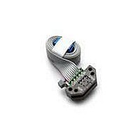
HEDS-9041-J00 Avago Technologies US Inc., HEDS-9041-J00 Datasheet - Page 7

HEDS-9041-J00
Manufacturer Part Number
HEDS-9041-J00
Description
En,Rop=23.36mm,3Ch,1024CPR,Bt Ld
Manufacturer
Avago Technologies US Inc.
Series
HEDSr
Datasheet
1.HEDS-8905.pdf
(13 pages)
Specifications of HEDS-9041-J00
Encoder Type
Optical
Output Type
Quadrature with Index (Incremental)
Pulses Per Revolution
1024
Voltage - Supply
5VDC
Actuator Type
Codewheel Not Included
Detent
No
Built In Switch
No
Mounting Type
Chassis Mount
Orientation
Right Angle
Termination Style
Terminal Pins
Mounting Style
PCB
Supply Voltage
5 V
Product
Optical
Lead Free Status / RoHS Status
Lead free / RoHS Compliant
Rotational Life (cycles Min)
-
Lead Free Status / Rohs Status
Lead free / RoHS Compliant
Available stocks
Company
Part Number
Manufacturer
Quantity
Price
Company:
Part Number:
HEDS-9041-J00
Manufacturer:
TI
Quantity:
340
Electrical Interface
To insure reliable encoding performance, the HEDS-9040
and 9140 three channel encoder modules require 2.7
kΩ (±10%) pull-up resistors on output pins 2, 3, and 5
(Channels I, A and B) as shown in Figure 1. These pull-up
resistors should be located as close to the encoder mod-
ule as possible (within 4 feet). Each of the three encoder
module outputs can drive a single TTL load in this con-
fi guration.
Figure 2. HEDS-9X40 Mounting Tolerance.
7
Figure 1. Pull-up Resistors on HEDS-9X40 Encoder Module Outputs.
Mounting Considerations
Figure 2 shows a mounting tolerance requirement for
proper operation of the HEDS-9040 and HEDS-9140. The
Aligning Recess Centers must be located within a toler-
ance circle of 0.005 in. radius from the nominal locations.
This tolerance must be maintained whether the module
is mounted with side A as the mounting plane using
aligning pins (see Figure 5), or mounted with Side B as
the mounting plane using an alignment tool (see Figures
3 and 4).


