43020-0200 Molex Inc, 43020-0200 Datasheet - Page 2
43020-0200
Manufacturer Part Number
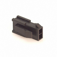
43020-0200
Description
CONN PLUG 2POS 3MM DUAL PNL MNT
Manufacturer
Molex Inc
Series
Micro-Fit 3.0™ 43020r
Type
Cable Plugr
Specifications of 43020-0200
Pitch
0.118" (3.00mm)
Number Of Rows
2
Connector Type
Plug
Contact Type
Male Pin
Number Of Positions
2
Row Spacing
0.118" (3.00mm)
Mounting Type
Panel Mount, Snap-In
Contact Termination
Crimp
Fastening Type
Ramp
Color
Black
Note
Contacts Not Provided
Product Type
Plugs - Housings
Contact Gender
Pin (Male)
Number Of Positions / Contacts
2
Mounting Style
Free Hanging
Mounting Angle
Vertical
Termination Style
Crimp
Housing Material
Polyester
Voltage Rating
350 V
Current Rating
5 A
Agency Approvals
CSA, UL, TUV
Angle
Straight
Brand/series
Micro-Fit 3.0™/43020 Series
Flammability Rating
UL94V-0
Length, Overall
0.665 "
Material, Housing
Polyester
Number Of Contacts
2
Pin Spacing
0.118 "
Primary Type
Interconnect System
Temperature, Operating
-40 to +105 °C
Lead Free Status / RoHS Status
Lead free / RoHS Compliant
Features
-
Lead Free Status / Rohs Status
Lead free / RoHS Compliant
Other names
0430200200
430-20-0200-P
43020-0200-P
WM1777
430-20-0200-P
43020-0200-P
WM1777
Available stocks
Company
Part Number
Manufacturer
Quantity
Price
Company:

Part Number:
43020-0200
Manufacturer:
MOLEX
Quantity:
40 000
Company:
Part Number:
43020-0200
Manufacturer:
MOLEX
Quantity:
16 000
Company:
Part Number:
43020-0200
Manufacturer:
SMD
Quantity:
35 000


REVISION:
DOCUMENT NUMBER:
5.0 TESTING PROCEDURES
A
5.1 TERMINAL RETENTION FORCE
5.2 THUMB LATCH TO RAMP YIELD STRENGTH
5.3 THUMB LATCH DURABILITY/CYCLING
TS-43045-003
Microfit 43030 and 43031 terminals were crimped to 20 awg wires and inserted into receptacle
and plug housings, respectively. All circuits were populated. An axial pullout force was applied to
each terminal by pulling on the wire at a rate of 1.0 inch per minute. The maximum force to
dislodge each terminal from the housing was recorded.
Receptacles were mated to header housings to fully engage latches. Header housings were
secured to the base table and the receptacle housings were secured within a grip fixture attached
to the load cell of a motorized force testing device. The crosshead of the device was then moved
in the direction of unmating at a rate of 1.0 inch per minute until the latching geometry of either
the receptacle or the header housing yielded. The maximum force to yield the latch was
recorded.
The thumb latch on the receptacle was first deflected to its extreme until it contacted the body of
the housing (wire insertion side). It was then deflected to its opposite extreme until it contacted
the towers of the housing (mating side). This defined one cycle of the latch. Increments of 5
cycles were repeated on the latch. After each 5 cycle increment the receptacle was mated to a
plug and proper latch engagement was confirmed. Testing was terminated after 50 cycles since
no latch integrity failures were observed and this surpassed the 30 mating cycle rating for these
products by 67%.
ECR/ECN INFORMATION:
EC No:
DATE:
08/12/10
TEST SUMMARY
TITLE:
CREATED / REVISED BY:
SSOUSEK
MICRO-FIT (3.0) CONNECTOR SERIES
NYLON 6 RECEPTACLES AND PLUGS
TEST SUMMARY
CHECKED BY:
JBELL
TEMPLATE FILENAME: TEST_SUMMARY[SIZE_A](V.1).DOC
APPROVED BY:
FSMITH
SHEET No.
2
of
3
Related parts for 43020-0200
Image
Part Number
Description
Manufacturer
Datasheet
Request
R

Part Number:
Description:
CONN PLUG 4POS 3MM DUAL PNL MNT
Manufacturer:
Molex Inc
Datasheet:

Part Number:
Description:
CONN PLUG 6POS 3MM DUAL PNL MNT
Manufacturer:
Molex Inc
Datasheet:

Part Number:
Description:
CONN PLUG 12POS 3MM DUAL PNL MNT
Manufacturer:
Molex Inc
Datasheet:

Part Number:
Description:
CONN PLUG 14POS 3MM DUAL ROW
Manufacturer:
Molex Inc
Datasheet:

Part Number:
Description:
Plug Housing
Manufacturer:
Molex Inc
Datasheet:
