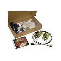
AFBR-0978Z Avago Technologies US Inc., AFBR-0978Z Datasheet

AFBR-0978Z
Specifications of AFBR-0978Z
AFBR-0978Z
Related parts for AFBR-0978Z
AFBR-0978Z Summary of contents
Page 1
... Factory automation at Fast Ethernet speeds • Fast Ethernet networking over POF and HCS • Link Distance POF or 100 m HCS (See application note 5290 for details) HCS® trademark of OFS Corporation AFBR-5978Z is compatible with the SC-RJ Connecting System from Reichle & De-Massari AG, Switzerland ...
Page 2
Block diagram ELECTRICAL SUBASSEMBLY DIFFERENTIAL DATA OUT SINGLE-ENDED SIGNAL QUANTIZER IC DETECT OUT DMI DIFFERENTIAL DATA IN DRIVER IC Figure 1. Block diagram The optical subassemblies utilize a high volume assem- bly process together with low cost lens elements which ...
Page 3
Pin Descriptions Pin 1 Sda: the data line of the two wire serial interface. This data line should be pulled up with a 4.7k–10kΩ resis- tor on the host board to a supply of 3.3V ±10%. Pin 2 Rx GND: ...
Page 4
... DC-biasing resistor can be selected by as- suming current. This results in a bias-resistor value of 142Ω - 200Ω. After the AC-coupling capacitors, a Thèvenin equivalent transformation connects to the LVPECL compatible network interface, equal to the one used in DC-coupling. TxVcc AFBR-5978Z Txdis 10nF LED driver 10nF RxVcc Rdata+ Amplifier & ...
Page 5
... Digital Diagnostics Monitoring Interface The AFBR-5978Z transceiver features an enhanced digital diagnostic interface, compliant to the “Digital Diagnostic Monitoring Interface for Optical Transceivers” SFF-8472 Multi-source Agreement (MSA). Please refer to the MSA document to access information on the range of options, both hardware and software, available to the host system for exploiting the available digital diagnostic features ...
Page 6
Table 1. Transceiver soft diagnostics Timing characteristics Parameter Hardware TX_DISABLE assert time Hardware TX_DISABLE negate time Time to initialize Hardware RX_SD assert time Hardware RX_SD de-assert time Software TX_DISABLE assert time Software TX_DISABLE negate time Software RX_SD assert time Software ...
Page 7
Table 2. Transceiver Digital Diagnostic Monitor Characteristics Parameter Symbol Transceiver internal T INT temperature accuracy Transceiver internal V INT supply voltage accuracy V > 2. TX_DISABLE Transmitted Signal t_init t-init: TX_DISABLE NEGATED occurrence Optical Signal of loss SD ...
Page 8
Table 3. EEPROM Serial ID Memory Contents – Address A0h Addr Hex ASCII Description ...
Page 9
... Received OMA margin is decoded bit signed twos compliment integer in increments of 0.2 dB. 5. This register is read only. A write will be acknowledged but not stored. 6. Bytes 56-94 are not intended for use with AFBR-5978Z, but have been set to default values per SFF-8472. 7. Byte checksum calculated (per SFF-8472) and stored prior to product shipment. ...
Page 10
... Data Ready (Bar) Notes: 1. The response time for soft commands of the AFBR-5978Z is 100 ms as specified by the MSA SFF-8472. 2. Bit 6 is logic OR’d with the TX_DISABLED input pin. Either asserted will disable the transmitter. 3. Reserved bits will return “0” when read. A write to a reserved bit will be acknowledged but not stored. ...
Page 11
Regulatory Compliance Table Feature Test Method MIL-STD 883 Method 3015, 100 pulse per polarity IEC 61000-4-2 Typically withstand an electrostatic discharge without dam- age when the SC-RJ connector receptacle is contacted by a Human Body ...
Page 12
Recommended Operating Conditions Parameter Case Operating Temperature Supply Voltage Differential Input Voltage Data and Signal Detect Output Load Signalling rate (Fast-Ethernet) Signalling rate (Ethernet) Humidity Notes: 5. Ethernet and Fast Ethernet optical auto-negotiation signals over a 1 MHz carrier are ...
Page 13
Transmitter Optical Characteristics Parameter Average Launched Power (1mm POF, NA=0.5) Average Launched Power (200um HCS, NA=0.37) Optical Modulation Amplitude (POF) Optical Modulation Amplitude (HCS) Central Wavelength Spectrum RMS Optical Rise Time (10%-90%) Optical Fall Time (10%-90%) Duty Cycle Distortion Contributed ...
Page 14
Receiver Electrical Characteristics Parameter Data Output Voltage - Low Data Output Voltage - High Data Output Voltage Swing Data Output Rise Time Data Output Fall Time Duty Cycle Distortion Data Dependent Jitter (rise/fall) Random Jitter Signal Detect Output Voltage - ...


