LTST-S270KSKT Lite-On Electronics, LTST-S270KSKT Datasheet - Page 9
LTST-S270KSKT
Manufacturer Part Number
LTST-S270KSKT
Description
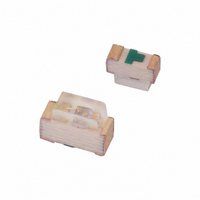
SMT LED YELLOW CLEAR
Manufacturer
Lite-On Electronics
Type
Uni-Colorr
Specifications of LTST-S270KSKT
Package / Case
0603 (1608 Metric)
Viewing Angle
130°
Color
Yellow
Millicandela Rating
80mcd
Current - Test
20mA
Wavelength - Dominant
587nm
Wavelength - Peak
588nm
Voltage - Forward (vf) Typ
2V
Lens Type
Clear
Lens Style/size
Rectangle, 1.2mm x 0.6mm
Size / Dimension
1.60mm L x 1.15mm W
Height
0.60mm
Mounting Type
Surface Mount, Right Angle
Resistance Tolerance
587nm
Led Size
1.6 mm x 0.6 mm
Illumination Color
Yellow
Lens Color/style
Water Clear
Operating Voltage
2 V
Wavelength
589 nm
Luminous Intensity
60 mcd
Mounting Style
SMD/SMT
Operating Current
20 mA
Lens Shape
Rectangular
Maximum Operating Temperature
+ 85 C
Minimum Operating Temperature
- 55 C
Peak Wavelength
591 nm
Number Of Leds
1
Led Material
AlGaInP
Intensity
80 mcd
Dominant Wavelength
587 nm
Lens Appearance
Colorless Non Diffused
Lens Shape Type
Rectangular
Mounting Orientation
Top Mount
Package Type
Chip Led
Emitting Color
Amber
Test Current (it)
20mA
Forward Current
30mA
Dominant Wave Length
587nm
Forward Voltage
2.4V
Product Length (mm)
1.6mm
Product Height (mm)
1.15mm
Product Depth (mm)
0.6mm
Mounting
Surface Mount
Shape Type
Rectangular
Chip Material
AlGaInP
Main Category
Chip LED
Number Of Elements
1
Pin Count
2
Operating Temperature Classification
Industrial
Operating Temp Range
-55C to 85C
Reverse Voltage
5V
Power Dissipation
75mW
Lens Dimensions
1.2X0.6X0.47mm
Lead Free Status / RoHS Status
Lead free / RoHS Compliant
Luminous Flux @ Current - Test
-
Lead Free Status / Rohs Status
Lead free / RoHS Compliant
Other names
160-1480-2
LTSTS270KSKT
LTSTS270KSKT
Available stocks
Company
Part Number
Manufacturer
Quantity
Price
Company:

Part Number:
LTST-S270KSKT
Manufacturer:
LITEON
Quantity:
40 000
Company:
Part Number:
LTST-S270KSKT
Manufacturer:
Lite-On Inc
Quantity:
30 853


BNS-OD-C131/A4
Part No. : LTST-S270KSKT
1. Application
2. Storage
3. Cleaning
4. Soldering
5. Drive Method
6. ESD (Electrostatic Discharge)
Static Electricity or power surge will damage the LED.
Suggestions to prevent ESD damage:
(A) Recommended circuit.
The LEDs described here are intended to be used for ordinary electronic equipment (such as office
equipment, communication equipment and household applications).Consult Liteon’s Sales in advance
for information on applications in which exceptional reliability is required, particularly when the failure
or malfunction of the LEDs may directly jeopardize life or health (such as in aviation, transportation,
traffic control equipment, medical and life support systems and safety devices).
The storage ambient for the LEDs should not exceed 30°C temperature or 70% relative humidity.
It is recommended that LEDs out of their original packaging are IR-reflowed within one week.
For extended storage out of their original packaging, it is recommended that the LEDs be stored in a
sealed container with appropriate desiccant, or in a desiccators with nitrogen ambient.
LEDs stored out of their original packaging for more than a week should be baked at about 60 deg C
for at least 24 hours before solder assembly.
Use alcohol-based cleaning solvents such as isopropyl alcohol to clean the LED if necessary.
Recommended soldering conditions:
An LED is a current-operated device. In order to ensure intensity uniformity on multiple LEDs
connected in parallel in an application, it is recommended that a current limiting resistor be incorporated
in the drive circuit, in series with each LED as shown in Circuit A below.
(B) The brightness of each LED might appear different due to the differences in the I-V characteristics
Pre-heat
Pre-heat time
Peak temperature
Soldering time
Use of a conductive wrist band or anti-electrostatic glove when handling these LEDs.
All devices, equipment, and machinery must be properly grounded.
Work tables, storage racks, etc. should be properly grounded.
Use ion blower to neutralize the static charge which might have built up on surface of the LED’s
plastic lens as a result of friction between LEDs during storage and handling.
of those LEDs.
Reflow soldering
Circuit model A
120~150°C
120 sec. Max.
240°C Max.
10 sec. Max.
LITE-ON TECHNOLOGY CORPORATION
LED
P r o p e r t y o f L i t e - O n O n l y
Pre-heat
Pre-heat time
Solder wave
Soldering time
CAUTIONS
Wave Soldering
100°C Max.
60 sec. Max.
260°C Max.
10 sec. Max.
Circuit model B
LED
Temperature
Soldering time
Page :
Soldering iron
9
300°C Max.
3 sec. Max.
(one time only)
of
11
Related parts for LTST-S270KSKT
Image
Part Number
Description
Manufacturer
Datasheet
Request
R

Part Number:
Description:
LED GREEN CLEAR 1206 SMD
Manufacturer:
Lite-On Electronics
Datasheet:

Part Number:
Description:
LED GREEN CLEAR 0603 SMD
Manufacturer:
Lite-On Electronics
Datasheet:

Part Number:
Description:
LED GREEN/YEL BICOLOR 1210 SMD
Manufacturer:
Lite-On Electronics
Datasheet:

Part Number:
Description:
LED 468NM RA BLUE CLEAR 0603 SMD
Manufacturer:
Lite-On Electronics
Datasheet:

Part Number:
Description:
LED'S
Manufacturer:
Lite-On Electronics
Datasheet:

Part Number:
Description:
LED'S
Manufacturer:
Lite-On Electronics
Datasheet:

Part Number:
Description:
SMT LED RED CLEAR
Manufacturer:
Lite-On Electronics
Datasheet:

Part Number:
Description:
Standard LED - SMD Green Clear 525nm
Manufacturer:
Lite-On Electronics
Datasheet:
Part Number:
Description:
Standard LED - SMD Green/Red Clear 571nm/631nm
Manufacturer:
Lite-On Electronics
Datasheet:
Part Number:
Description:
Standard LED - SMD Red Clear 638nm
Manufacturer:
Lite-On Electronics
Datasheet:

Part Number:
Description:
LED RED ORAN CLR 0603 RT ANG SMD
Manufacturer:
Lite-On Electronics
Datasheet:

Part Number:
Description:
LED GREEN CLEAR 1206 SMD
Manufacturer:
Lite-On Electronics
Datasheet:

Part Number:
Description:
LED BLUE CLEAR THIN 0603 SMD
Manufacturer:
Lite-On Electronics
Datasheet:

Part Number:
Description:
LED BLUE CLEAR 0805 SMD
Manufacturer:
Lite-On Electronics
Datasheet:

Part Number:
Description:
LED 468NM BLUE CLEAR DOME SMD
Manufacturer:
Lite-On Electronics
Datasheet: