LMR4769EW-WCB DENSITRON, LMR4769EW-WCB Datasheet - Page 69
LMR4769EW-WCB
Manufacturer Part Number
LMR4769EW-WCB
Description
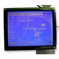
LCD MODULE, 240X320, BLUE
Manufacturer
DENSITRON
Datasheet
1.LMR4769EW-WCB.pdf
(108 pages)
Specifications of LMR4769EW-WCB
Lcd Display Type
STN
Pixel Size (h X W)
0.34mm X 0.34mm
Display Mode
Transflective
Interface Type
Serial
Viewing Area (h X W)
92.14mm X 120.14mm
Supply Voltage
32V
External Depth
15.6mm
External
RoHS Compliant
Svhc
No SVHC (15-Dec-2010)
Rohs Compliant
Yes
Backlighting Colour
Blue
Pixel Pitch (h X W)
0.36mm X 0.36mm


4: FUNCTION DESCRIPTION
4.1.6
64
Number of pixels
320 x 240
(X x Y)
(1) Determining FX
(2) Determining C/R
(3) Determining TC/R
(4) Relationship between f
(5) Symptoms observed when TC/R is set incorrectly
Determining Various Parameters
Note: 1. If standard crystals close to f
Note: 1. Because the number of display dots varies with each LCD unit, there will be some frac-
Determine the character field size in the X direction [FX] from the number of dots in the X direction of
display [VD] and the number of characters in the X direction [VC].
The brackets [ ] denote an integral value beginning with 1, and [FX] indicates the number of dots.
Next, determine a value for [C/R] from the values of [VC] and [FX].
Note: [C/R] indicates the number of characters obtained in units of addresses.
TC/R must maintain the relationship [TC/R] [C/R] + 4.
Once TC/R has been determined, the lower-limit value of the oscillation frequency (f
from the equation below because the frame frequency (f
predetermined.
• Scanning of display in the Y direction stops, with horizontal lines displayed in high contrast.
• All pixels go on or go off.
• The LP pin output signal is incomplete or inactive.
• The display of graphics or text becomes unstable.
Should any of the symptoms above be observed, even though the S1D13700’s other signals connected to
the LCD unit are normal, check whether the TC/R value is correct. If the TC/R value is the cause of the
problem, simply set a larger TC/R value to restore normal operation.
[VD] / [VC] [FX]
[C/R] = | [FX] / 8 | rounded up x [VC]
f
OSC
2. For the f
2. Calculations are made assuming f
e.g., [FX] = 8 dots
320
No blank dots
e.g., [FX] = 6 dots
320
Two blank dots
ate f
do so, reverse the calculation of the [TC/R] value in the equation above.
tional display dots depending on the value set for FX. In such case, the S1D13700 auto-
matically blanks fractional parts at the right edge of the panel, and thus eliminates the
need to manipulate display memory for adjustment.
{[TC/R] x 9 + 1} x [L/F] x f
8 = 40...0
6 = 53...2
[FX]
OSC
FR
value for crystals with higher oscillation frequencies than the obtained value. To
Table 4-2 Example of Parameters for the LCD Unit
value of Epson LCD units, refer to the LCD unit specifications.
OSC
From a practical
point of view, 8, 16,
etc. are suitable.
and f
FR
[FY]
FR
OSC
EPSON
thus obtained are unavailable, determine the appropri-
[CR] = 40 = address
During HDOT SCR, [C/R] = 41 addresses
[CR] = 53 = address
During HDOT SCR, [C/R] = 54 addresses
FR
= 60 Hz.
FR
) and number of display lines [L/F] are
[C/R]
27H
34H
S1D13700 Technical Manual
OSC
TC/R
2BH
38H
) can be obtained
(MHz)
X'tal
5.72
7.40
Related parts for LMR4769EW-WCB
Image
Part Number
Description
Manufacturer
Datasheet
Request
R

Part Number:
Description:
LCD MODULE, 128X240, YELLOW/GREEN
Manufacturer:
DENSITRON
Datasheet:

Part Number:
Description:
LCD MODULE, 128X240, BLUE
Manufacturer:
DENSITRON
Datasheet:

Part Number:
Description:
PMOLED, 128*128, COLOUR
Manufacturer:
DENSITRON
Datasheet:

Part Number:
Description:
DISPLAY, OLED, 128X32, BLUE
Manufacturer:
DENSITRON
Datasheet:
Part Number:
Description:
DISPLAY, OLED, 128X32, YLW
Manufacturer:
DENSITRON
Datasheet:
Part Number:
Description:
PMOLED, 128*64, WHITE
Manufacturer:
DENSITRON
Datasheet:
Part Number:
Description:
DISPLAY, OLED, 128X64, YELLOW
Manufacturer:
DENSITRON
Datasheet:

Part Number:
Description:
DISPLAY, OLED, 128X64, YELLOW
Manufacturer:
DENSITRON
Datasheet:
Part Number:
Description:
DISPLAY, OLED, 128X64, YELLOW
Manufacturer:
DENSITRON
Datasheet:
Part Number:
Description:
128 x 240 PIXEL INDUSTRIAL TOUCH MONITOR
Manufacturer:
Densitron Corporation
Part Number:
Description:
64 x 240 PIXEL INDUSTRIAL TOUCH MONITOR
Manufacturer:
Densitron Corporation
Part Number:
Description:
320 x 240 PIXEL INDUSTRIAL TOUCH MONITOR
Manufacturer:
Densitron Corporation
Part Number:
Description:
320 x 240 PIXEL INDUSTRIAL TOUCH MONITOR
Manufacturer:
Densitron Corporation
Part Number:
Description:
132 Seg / 65 Com Driver & Controller For Stn Lcd
Manufacturer:
Densitron Corporation
Datasheet: