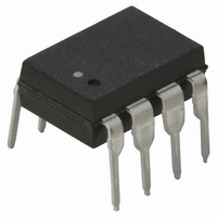
HCPL-7601 Avago Technologies US Inc., HCPL-7601 Datasheet - Page 11

HCPL-7601
Manufacturer Part Number
HCPL-7601
Description
OPTOCOUPLER, TRANSISTOR, 3750VRMS
Manufacturer
Avago Technologies US Inc.
Datasheet
1.HCPL-7611.pdf
(13 pages)
Specifications of HCPL-7601
No. Of Channels
1
Optocoupler Output Type
Transistor
Input Current
10mA
Output Voltage
7V
Opto Case Style
DIP
No. Of Pins
8
Propagation Delay Low-high
100ns
Isolation Voltage
3.75kV
Voltage - Isolation
3750Vrms
Number Of Channels
1, Unidirectional
Current - Output / Channel
50mA
Data Rate
10MBd
Propagation Delay High - Low @ If
57ns @ 4mA
Current - Dc Forward (if)
20mA
Input Type
DC
Output Type
Open Collector
Mounting Type
Through Hole
Package / Case
8-DIP (0.300", 7.62mm)
Lead Free Status / RoHS Status
Contains lead / RoHS non-compliant
Other names
516-1098-5
Available stocks
Company
Part Number
Manufacturer
Quantity
Price
Company:
Part Number:
HCPL-7601
Manufacturer:
AGILENT
Quantity:
28
Part Number:
HCPL-7601
Manufacturer:
AVAGO/安华高
Quantity:
20 000
Company:
Part Number:
HCPL-7601-000E
Manufacturer:
AVAGO
Quantity:
10 000
Part Number:
HCPL-7601-000E
Manufacturer:
AVAGO/安华高
Quantity:
20 000
Company:
Part Number:
HCPL-7601-300E
Manufacturer:
AVAGO
Quantity:
10 000
Part Number:
HCPL-7601-300E
Manufacturer:
AVAGO/安华高
Quantity:
20 000
Company:
Part Number:
HCPL-7601-500E
Manufacturer:
AVAGO
Quantity:
40 000
Part Number:
HCPL-7601-500E
Manufacturer:
AVAGO/安华高
Quantity:
20 000
Figure 12. Pulse width distortion vs. input
current.
Figure 7. Test circuit for t
Figure 9. t
temperature.
11
MONITORING
PULSE GEN.
t
f
Z
= t
O
100
-10
-20
-30
-40
-50
-60
-70
90
80
70
60
50
40
30
30
20
10
= 50
r
0
-50
= 5 ns
INPUT
*C
NODE
0
OUTPUT
L
PHL
V
R
T
INPUT
-30
IS APPROXIMATELY 15 pF WHICH INCLUDES
PROBE AND STRAY WIRING CAPACITANCE.
A
CC
L
T
– Propagation delay vs.
I
= 350 – 4 k
= 25° C
I
I
2
I
V
F
F
F
F
A
= 5 V
O
R
– INPUT CURRENT – mA
= 2 mA
= 4 mA
I
F
-10
– TEMPERATURE – °C
M
4
0
10
t
PHL
1
2
3
4
PHL
6
R
R
R
V
T
30
L
L
L
A
and t
CC
= 350
= 1 k
= 4 k
= 25° C
8
= 5 V
50
PLH
.
10
70
GND
V
CC
12
t
90
PLH
8
7
6
5
Figure 10. Propagation delay vs. input
current.
Figure 13. Rise and fall time vs. temperature.
120
110
100
330
320
310
300
290
90
80
70
60
50
40
30
60
40
20
0.1µF
BYPASS
0
-60 -40 -20
1
1.5 V
I
50% I
F
V
I
2
F
*C
CC
T
T
T
PLH
PLH
= 2 – 4 mA
I
R
R
R
R
F
L
PHL
+5 V
3
= 5.0 V
F
L
L
L
L
– INPUT CURRENT – mA
T
= 4 k
= 1 k
= 350
= 350 , 1 k , 4 k
A
@ R
@ R
@ R
4
R
– TEMPERATURE – °C
L
0
L
L
5
L
OUTPUT V
MONITORING
NODE
= 4 k
= 350
= 350 – 4 k
20
6
T
PLH
7
40
t
t
FALL
RISE
@ R
O
8
V
T
60
A
CC
L
9
= 25° C
= 1 k
= 5 V
80 100
10
11
Figure 8. t
temperature.
Figure 11. Pulse width distortion vs.
temperature.
120
110
100
-30
-15
-45
-60
90
80
70
60
50
40
30
30
15
0
-50
-50
PLH
I
I
I
V
T
F
F
F
-30 -10
-30
A
CC
= 2 mA, R
= 4 mA, R
= 4 mA, R
– Propagation delay vs.
T
I
I
I
T
F
F
F
A
A
= 25° C
= 2-4 mA, R
= 2-4 mA, R
= 2-4 mA, R
= 5 V
– TEMPERATURE – °C
-10
– TEMPERATURE – °C
I
I
F
F
0
0
= 2 mA, R
= 2 mA, R
L
L
L
10
10
I
= 1 k
F
= 1 k
= 4 k
= 4 mA, R
L
L
L
30
30
= 4 k
= 1 k
= 350
L
L
= 4 k
= 350
50
50
L
= 350
70
70
90
90


