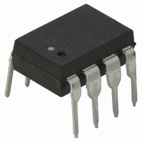
HCPL-2202 Avago Technologies US Inc., HCPL-2202 Datasheet

HCPL-2202
Specifications of HCPL-2202
Available stocks
Related parts for HCPL-2202
HCPL-2202 Summary of contents
Page 1
... HCPL-2201, HCPL-2202, HCPL-2211,HCPL-2212, HCPL-2231, HCPL-2232, HCPL-0201, HCPL-0211, HCNW2201, HCNW2211 Very High CMR, Wide V Logic Gate Optocouplers CC Data Sheet Lead (Pb) Free RoHS 6 fully compliant RoHS 6 fully compliant options available; -xxxE denotes a lead-free product Description The HCPL-22XX, HCPL-02XX, and HCNW22XX are optical- ly-coupled logic gates. The HCPL-22XX, and HCPL-02XX contain a GaAsP LED while the HCNW22XX contains an AlGaAs LED ...
Page 2
... CMOS logic and result in lower power consump tion compared to other high speed couplers. Logic signals are transmitted with a typical propagation delay of F 150 ns. Single Dual Channel Channel Package Package HCPL-2200 [1,2] HCPL-2201 HCPL-2202 HCPL-2231 HCPL-2219 [1,2] HCPL-2211 HCPL-2212 HCPL-2232 , – ...
Page 3
... To order, choose a part number from the part number column and combine with the desired option from the option column to form an order entry. Example 1: HCPL-2202-560E to order product of 300mil DIP Gull Wing Surface Mount package in Tape and Reel packaging with IEC/EN/DIN EN 60747-5-2 Safety Approval in RoHS compliant. Example 2: HCPL-2202 to order product of 300mil DIP package in tube packaging and non RoHS compliant ...
Page 4
... TYPE NUMBER A XXXXZ YYWW 1.19 (0.047) MAX. 3.56 ± 0.13 (0.140 ± 0.005) 1.080 ± 0.320 (0.043 ± 0.013) 8-Pin DIP Package with Gull Wing Surface Mount Option 300 (HCPL-2201/02/11/12/31/32) 9.65 ± 0.25 (0.380 ± 0.010 1.19 (0.047) MAX. 1.080 ± 0.320 (0.043 ± ...
Page 5
... Small-Outline SO-8 Package (HCPL-0201/11 XXX 3.937 ± 0.127 YWW (0.155 ± 0.005 PIN ONE 0.406 ± 0.076 (0.016 ± 0.003) * 5.080 ± 0.127 (0.200 ± 0.005) 3.175 ± 0.127 (0.125 ± 0.005) * TOTAL PACKAGE LENGTH (INCLUSIVE OF MOLD FLASH) 5.207 ± 0.254 (0.205 ± 0.010) DIMENSIONS IN MILLIMETERS (INCHES) ...
Page 6
Widebody DIP Package with Gull Wing Surface Mount Option 300 (HCNW2201/11) 11.23 ± 0.15 (0.442 ± 0.006 1.55 (0.061) MAX. 1.80 ± 0.15 (0.071 ± 0.006) 2.54 (0.100) BSC DIMENSIONS IN ...
Page 7
... PREHEAT 60 to 180 SEC °C to PEAK TIME Regulatory Information The HCPL-22XX/02XX and HCNW22XX have been approved by the following organizations: UL Recognized under UL 1577, Component Recognition Program, File E55361. CSA Approved under CSA Component Acceptance Notice #5, File CA 88324. Insulation and Safety Related Specifications ...
Page 8
... IEC/EN/DIN EN 60747-5-2 Insulation Related Characteristics (HCPL-2211/2212 Option 060 ONLY) Description Installation classification per DIN VDE 0110/1.89, Table 1 for rated mains voltage ≤300 V rms for rated mains voltage ≤450 V rms Climatic Classification Pollution Degree (DIN VDE 0110/1.89) Maximum Working Insulation Voltage Input to Output Test Voltage, Method ...
Page 9
IEC/EN/DIN EN 60747-5-2 Insulation Related Characteristics (HCNW22XX ONLY) Description Installation classification per DIN VDE 0110/1.89, Table 1 for rated mains voltage ≤600 V rms for rated mains voltage ≤1000 V rms Climatic Classification Pollution Degree (DIN VDE 0110/1.89) Maximum Working ...
Page 10
... Symbol F(AVG) I F(TRAN) HCNW22XX V R HCNW22XX HCPL-223X P O 260°C for 10 sec., 1.6 mm below seating plane HCNW22XX 260°C for 10 sec seating plane See Package Outline Drawings section Symbol F(ON) HCPL-223X V F(OFF Min. Max. Units Note -55 125 °C -40 85 ° 1 -0.5 20 ...
Page 11
... Logic Low Short Circuit Output Current Logic High Short Circuit Output Current Input Forward Voltage HCNW22XX Input Reverse Breakdown Voltage HCNW22XX Input Diode Temperature Coefficient HCNW22XX Input Capacitance HCNW22XX *For HCPL-223X, 1.8 mA ≤ I ≤ 5 mA. F(ON) **Typical 2 ≤ ≤ V F(ON) F(OFF) Sym. Min. ...
Page 12
... HCPL-2232 HCNW2211 Logic Low |CM | HCPL-2201/02 L Common Mode HCPL-0201 Transient HCPL-2231 Immunity HCNW2201 HCPL-2211/12 HCPL-0211 HCPL-2232 HCNW2211 *For HCPL-223X, 1.8 mA ≤ I ≤ 5 mA. F(ON) †I = 1.8 mA for HCPL-2231. F ‡I = 1.8 mA for HCPL-2232 ≤ ≤ F(ON) F(OFF unless otherwise specified. F(ON) Sym. ...
Page 13
... the maximum slew rate of the common mode voltage that can be sustained with the output voltage in the logic low state For HCPL-2202/12 pin Use of a 0.1 µF bypass capacitor connected between pins 5 and 8 is recommended. 10. In accordance with UL 1577, each optocoupler is proof tested by applying an insulation test voltage ≥4500 V rms for one second (leakage ≤ ...
Page 14
... Figure 2. Typical logic high output current vs. temperature. HCPL-2201 fig 2 HCNW22XX 1000 100 – 1.0 0.1 0.01 0.001 1.1 1.2 1.3 1.4 V – FORWARD VOLTAGE – HCPL-2201 fig 4b PULSE GEN 100 kHz OUTPUT DUTY MONITORING NODE 5 V 619 Ω INPUT MONITORING NODE ...
Page 15
... SWITCH OUTPUT V SWITCH (MAX.)* O V (MAX.)* SEE NOTE SEE NOTE 1.8 mA FOR HCPL-2231/32 DEVICES 1.8 mA FOR HCPL-2231/32 DEVICES. F HCPL-2201 fig 10c HCPL-2201 fig 10c ° 100 – SUPPLY VOLTAGE – Figure 7. Maximum output power per channel vs. supply voltage. HCPL-2201 fig 7 ...
Page 16
... HCPL-2201 fig 11b HCNW22XX 1000 P (mW) S 900 I (mA) S 800 700 600 500 400 300 200 100 100 125 T – CASE TEMPERATURE – °C S HCPL-2201 fig 12b HCPL-2201/11 HCPL-02XX HCNW22XX V CC2 8 DATA OUTPUT LSTTL LOADS TTL LOADS 2 HCPL-2201 fig 13a 80 100 150 175 (+5 V) ...
Page 17
... GND 4 5 from the LED (+5 V) CC2 DATA OUTPUT LSTTL LOADS OR 4 TTL LOADS HCPL-2201/11 V (+5 V) CC1 1.1 kΩ 1 DATA 2 INPUT D1 TTL or 3 LSTTL 4 D1 (1N4150) REQUIRED FOR ACTIVE PULL-UP DRIVER. Figure 15. Alternative LED drive circuit. HCPL-2201 fig 15 HCPL-02XX HCNW22XX GND 5 ...
Page 18
For product information and a complete list of distributors, please go to our website: Avago, Avago Technologies, and the A logo are trademarks of Avago Technologies in the United States and other countries. Data subject to change. Copyright © 2005-2010 ...


