MOC8111 Vishay, MOC8111 Datasheet

OPTOCOUPLER, PHOTOTRANSISTOR, 5300VRMS

MOC8111

Manufacturer Part Number
MOC8111
Description
OPTOCOUPLER, PHOTOTRANSISTOR, 5300VRMS
Manufacturer
Vishay
Datasheet

Specifications of MOC8111

No. Of Channels
1
Optocoupler Output Type
Phototransistor
Input Current
10mA
Output Voltage
30V
Opto Case Style
DIP
No. Of Pins
6
Mounting Type
Through Hole
Isolation Voltage
5.3kV
Number Of Channels
1
Input Type
DC
Voltage - Isolation
5300Vrms
Current Transfer Ratio (min)
20% @ 10mA
Current - Output / Channel
50mA
Current - Dc Forward (if)
60mA
Vce Saturation (max)
400mV
Output Type
Transistor
Package / Case
6-DIP (0.300", 7.62mm)
Maximum Input Diode Current
60 mA
Maximum Reverse Diode Voltage
6 V
Output Device
Phototransistor
Configuration
1 Channel
Maximum Collector Emitter Voltage
30 V
Maximum Collector Emitter Saturation Voltage
0.4 V
Maximum Forward Diode Voltage
1.5 V
Maximum Collector Current
150 mA
Maximum Power Dissipation
150 mW
Maximum Operating Temperature
+ 100 C
Minimum Operating Temperature
- 55 C
Lead Free Status / RoHS Status
Lead free / RoHS Compliant
Voltage - Output
-
Current Transfer Ratio (max)
-
Lead Free Status / RoHS Status
Lead free / RoHS Compliant, Lead free / RoHS Compliant
Other names
MOC8111GI
MOC8111GI
MOC8111VS

Available stocks

Company
Part Number
Manufacturer
Quantity
Price
Part Number:
MOC8111
Manufacturer:
FAIRCHIL
Quantity:
19
Part Number:
MOC8111M
Manufacturer:
FAIRCHILD/仙童
Quantity:
20 000
Part Number:
MOC8111SR2M
Manufacturer:
FAIRCHILD/仙童
Quantity:
20 000
DESCRIPTION
The MOC8111/ MOC8112 is an optocoupler consisting of a
gallium arsenide infrared emitting diode optically coupled to
a silicon planar phototransistor detector in a plastic plug-in
DIP 6 pin package.
The coupling device is suitable for signal transmission
between two electrically separated circuits. The potential
difference between the circuits to be coupled should not
exceed the maximum permissible reference voltages.
In contrast to the IL1, the base terminal is not connected,
resulting
interference immunity.
Note
For additional information on the available options refer to option information.
Document Number: 83661
Rev. 1.5, 11-Jan-08
ORDER INFORMATION
ABSOLUTE MAXIMUM RATINGS
PARAMETER
INPUT
DC forward current
Reverse voltage
Surge forward current
Total power dissipation
OUTPUT
Emitter collector breakdown voltage
Collector current
Total power dissipation
i179009
in
MOC8111-X006
MOC8111-X007
MOC8112-X006
MOC8112-X007
MOC8112-X009
substantially
MOC8111
MOC8112
PART
Optocoupler, Phototransistor Output,
NC
C
improved
A
1
2
3
For technical questions, contact: optocoupler.answers@vishay.com
common
TEST CONDITION
No Base Connection
6
5
4
(1)
t ≤ 10 µs
t ≤ 10 µs
B
C
E
mode
FEATURES
• No base terminal connection for improved
• Long term stability
• Industry standard dual in line package
• Lead (Pb)-free component
• Component in accordance to RoHS 2002/95/EC
AGENCY APPROVALS
• UL1577, file no. E52744 system code H or J, double
• BSI IEC 60950; IEC 60065
• DIN EN 60747-5-2 (VDE 0884)/DIN EN 60747-5-5 pending
• CSA 93751
CTR > 20 %, DIP-6 400 mil (option 6)
CTR > 50 %, DIP-6 400 mil (option 6)
common mode interface immunity
and WEEE 2002/96/EC
protection
available with option 1
CTR > 20 %, SMD-6 (option 7)
CTR > 50 %, SMD-6 (option 7)
CTR > 50 %, SMD-6 (option 9)
SYMBOL
BV
P
P
I
CTR > 20 %, DIP-6
CTR > 50 %, DIP-6
FSM
V
I
I
I
diss
diss
ECO
C
C
F
R
REMARKS
MOC8111/MOC8112
Vishay Semiconductors
VALUE
100
150
150
6.0
2.5
60
30
50
www.vishay.com
UNIT
mW
mW
mA
mA
mA
V
A
V
1

Related parts for MOC8111

MOC8111 Summary of contents

Page 1

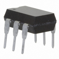
... NC 3 i179009 DESCRIPTION The MOC8111/ MOC8112 is an optocoupler consisting of a gallium arsenide infrared emitting diode optically coupled to a silicon planar phototransistor detector in a plastic plug-in DIP 6 pin package. The coupling device is suitable for signal transmission between two electrically separated circuits. The potential difference between the circuits to be coupled should not exceed the maximum permissible reference voltages ...

Page 2

... 1.0 MHz 1.0 µ CEO CEO µ ECO 1.0 MHz 500 µ CEsat TEST CONDITION PART MOC8111 mA MOC8112 TEST CONDITION SYMBOL = 100 Ω 2.0 mA, see figure 100 Ω off I = 2.0 mA, see figure 1 C VALUE 5300 ISO ≥ 7 ≥ 7 ≥ 4 175 ...

Page 3

... Option 7 0.300 (7.62) typ. 0.028 (0.7) min. 0.180 (4.6) 0.160 (4.1) 0.0040 (0.102) 0.0098 (0.249) 0.315 (8.0) min. 0.331 (8.4) min. 0.406 (10.3) max. MOC8111/MOC8112 Vishay Semiconductors Input pulse Output pulse off Waveforms ISO method A 0.300 (7.62) typ. 18 ° 0.114 (2.90) ...

Page 4

... MOC8111/MOC8112 Vishay Semiconductors OZONE DEPLETING SUBSTANCES POLICY STATEMENT It is the policy of Vishay Semiconductor GmbH to 1. Meet all present and future national and international statutory requirements. 2. Regularly and continuously improve the performance of our products, processes, distribution and operating systems with respect to their impact on the health and safety of our employees and the public, as well as their impact on the environment. ...

Page 5

... Vishay disclaims any and all liability arising out of the use or application of any product described herein or of any information provided herein to the maximum extent permitted by law. The product specifications do not expand or otherwise modify Vishay’ ...

Related keywords