BXRA-W5700-00S0E Bridgelux, BXRA-W5700-00S0E Datasheet - Page 25
BXRA-W5700-00S0E
Manufacturer Part Number
BXRA-W5700-00S0E
Description
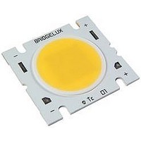
HIGH BRIGHTNESS LED, WARM WHITE, 5800LM
Manufacturer
Bridgelux
Series
Bridgelux RS Arrayr
Datasheet
1.BXRA-C5000-00E0C.pdf
(32 pages)
Specifications of BXRA-W5700-00S0E
Led Color
Warm White
Luminous Flux @ Test
5800lm
Cct
2870K
Forward Current @ Test
2.8A
Forward Current If Max
3.75A
Forward Voltage @ Test
30.9V
Rohs Compliant
Yes
Viewing Angle
120°
Available stocks
Company
Part Number
Manufacturer
Quantity
Price
Company:

Part Number:
BXRA-W5700-00S0E
Manufacturer:
Bridgelux
Quantity:
135


Mechanical Assembly and Handling
Recommended assembly is illustrated below.
When handling parts, please avoid contacting and do not apply stress to the resin area (see Figure 1,
resin area is indicated in yellow).
Product should be firmly secured onto appropriate heat sink by fastening M2.5, M3 or #4 screws on both
sides of the product as illustrated in Figure 19. To ensure proper thermal contact it is important to mount
the LED Array to the heat sink using 4 mounting screws. Bridgelux recommends the use of hard non-
electrically conductive flat washers with lock washers. The recommended center to center spacing for the
four tapped holes for mounting the Bridgelux RS Series Array is shown in Figure 20. Refer to Application
Note AN11 – Handling and Assembly of Bridgelux LED Arrays, for more details.
A thin layer of thermal grease should be applied to the bottom surface of the LED Array, between the
bottom of the LED Array and the heat sink. All air gaps and voids between the heat sink and array should
be eliminated. Ensure that sufficient thermal grease is used to cover the entire bottom surface of the
array, but not so much that the thermal grease creeps up to the top of the array.
Figure 19: Recommended Assembly Method
Drawing Not to Scale
Bridgelux RS Array Series Product Data Sheet DS16 (3/14/11)
Page 25 of 32
Related parts for BXRA-W5700-00S0E
Image
Part Number
Description
Manufacturer
Datasheet
Request
R

Part Number:
Description:
HIGH BRIGHTNESS LED, WARM WHITE, 6300LM
Manufacturer:
Bridgelux
Datasheet:
Part Number:
Description:
HIGH BRIGHTNESS LED, WARM WHITE, 5650LM
Manufacturer:
Bridgelux
Datasheet:
Part Number:
Description:
HIGH BRIGHTNESS LED, WARM WHITE, 5200LM
Manufacturer:
Bridgelux
Datasheet:

Part Number:
Description:
HIGH BRIGHTNESS LED, COOL WHITE, 5600LM
Manufacturer:
Bridgelux
Datasheet:
Part Number:
Description:
HIGH BRIGHTNESS LED,NEUTRAL WHITE,4400LM
Manufacturer:
Bridgelux
Datasheet:
Part Number:
Description:
HIGH BRIGHTNESS LED,NEUTRAL WHITE,7000LM
Manufacturer:
Bridgelux
Datasheet:
Part Number:
Description:
HIGH BRIGHTNESS LED, WARM WHITE, 4000LM
Manufacturer:
Bridgelux
Datasheet:
Part Number:
Description:
HIGH BRIGHTNESS LED, WARM WHITE, 3700LM
Manufacturer:
Bridgelux
Datasheet:
Part Number:
Description:
HIGH BRIGHTNESS LED, COOL WHITE, 8800LM
Manufacturer:
Bridgelux
Datasheet:
Part Number:
Description:
HIGH BRIGHTNESS LED, WARM WHITE, 3600LM
Manufacturer:
Bridgelux
Datasheet:
Part Number:
Description:
HIGH BRIGHTNESS LED, WARM WHITE, 3300LM
Manufacturer:
Bridgelux
Datasheet:

Part Number:
Description:
HIGH BRIGHTNESS LED, WARM WHITE, 295LM
Manufacturer:
Bridgelux
Datasheet:
Part Number:
Description:
HIGH BRIGHTNESS LED, WARM WHITE, 460LM
Manufacturer:
Bridgelux
Datasheet:
Part Number:
Description:
HIGH BRIGHTNESS LED, WARM WHITE, 460LM
Manufacturer:
Bridgelux
Datasheet:

Part Number:
Description:
56T4710
Manufacturer:
Bridgelux
Datasheet: