10-1114.1249 EAO, 10-1114.1249 Datasheet - Page 33
10-1114.1249
Manufacturer Part Number
10-1114.1249
Description
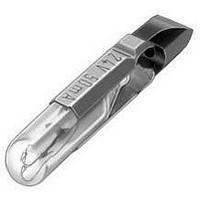
LAMP, INCANDESCENT, SLIDE, 30V
Manufacturer
EAO
Datasheet
1.10-1106.1369.pdf
(60 pages)
Specifications of 10-1114.1249
Supply Voltage
30V
Base Type
Telephone Slide
Bulb Size
T-5.5
Average Bulb Life
6000h
Lens Style
Tubular
Lead Style
Telephone Slide, T-5.5
Current Rating
40mA
Forward Voltage
30V
Lamp Base Type
Telephone Slide
Rohs Compliant
Yes
Lead Free Status / RoHS Status
Lead free / RoHS Compliant


Application guidelines
When switching inductive loads such as relays, DC motors, and DC solenoids, it is always important
to absorb surges (e.g. with a diode) to protect the contacts. When these inductive loads are switched
off, a counter emf can severely damage switch contacts and greatly shorten lifetime.
Fig. 1 shows an inductive load with a free-wheeling diode connected in parallel. This free-wheeling
diode provides a path for the inductor current to flow when the current is interrupted by the switch.
Without this free-wheeling diode, the voltage across the coil will be limited only by dielectric break-
down voltages of the circuit or parasitic elements of the coil. This voltage can be kilovolts in amplitude
even when nominal circuit voltages are low (e.g. 12 VDC) see Fig. 2.
The free-wheeling diode should be chosen so that the reverse breakdown voltage is greater than the
voltage driving the inductive load. The DC blocking voltage (VR) of the free-wheeling diode can be
found in the datasheet of a diode. The forward current should be equal or greater than the maximum
current flowing through the load.
To get an efficient protection, the free-wheeling diode must be connected as close as possible
to the inductive load!
0
VDC
Suppressor circuits
+
_
Switching with inductive load
Free-wheeling
Fig. 1
Switch
diode
Inductive
load
over load without free-wheeling diode
Sveral hundred
thousend volts
to several
Counter emf
0
Fig. 2
ON
OFF
e = L
__
dt
di
07.2009
31
14
Related parts for 10-1114.1249
Image
Part Number
Description
Manufacturer
Datasheet
Request
R

Part Number:
Description:
CONN HOUSING 5POS .100 HI PRESS
Manufacturer:
Molex Inc
Datasheet:

Part Number:
Description:
WIRE-BOARD CONN RECEPTACLE, 4POS, 2.54MM
Manufacturer:
Molex Inc
Datasheet:

Part Number:
Description:
WIRE-BOARD CONN RECEPTACLE 11POS, 2.54MM
Manufacturer:
Molex Inc
Datasheet:

Part Number:
Description:
CONN HOUSING 10POS .100 HI PRESS
Manufacturer:
Molex Inc
Datasheet:

Part Number:
Description:
CONN HOUSING 2POS .100 HI PRESS
Manufacturer:
Molex Inc
Datasheet:

Part Number:
Description:
CONN HOUSING 6POS .100 HI PRESS
Manufacturer:
Molex Inc
Datasheet:

Part Number:
Description:
CONN HOUSING 7POS .100 HI PRESS
Manufacturer:
Molex Inc
Datasheet:

Part Number:
Description:
CONN HOUSING 8POS .100 HI PRESS
Manufacturer:
Molex Inc
Datasheet:

Part Number:
Description:
CONN HOUSING 12POS .100 HI PRESS
Manufacturer:
Molex Inc
Datasheet:

Part Number:
Description:
WIRE-BOARD CONN RECEPTACLE, 9POS, 2.54MM
Manufacturer:
Molex Inc
Datasheet:

Part Number:
Description:
SINGLE CHIP LED/ T1 BI-PIN/ 2.1VDC/20MA - RED
Manufacturer:
EAO
Datasheet:

Part Number:
Description:
CRIMP HOUSING, 0.2", 10WAY
Manufacturer:
Molex Inc
Datasheet:
Part Number:
Description:
CONN HOUSING 5POS .100 HI PRESS
Manufacturer:
Molex Inc
Datasheet:

Part Number:
Description:
CONN HOUSING 2POS 5.08MM
Manufacturer:
Molex Inc
Datasheet:

Part Number:
Description:
CONN HEADER 2POS .084 VERT TIN
Manufacturer:
Molex Inc
Datasheet: