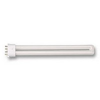
DSE984 OSRAM, DSE984 Datasheet - Page 54

DSE984
Manufacturer Part Number
DSE984
Description
LAMP, DULUX, S/E, CW, 9W
Manufacturer
OSRAM
Datasheet
1.DD1082.pdf
(82 pages)
Specifications of DSE984
Supply Voltage
230V
Base Type
2G7
Power Rating
8W
Luminous Flux
600lm
Length
144mm
Colour Temperature Typ
5000K
Svhc
No SVHC (15-Dec-2010)
External Diameter
21mm
Lamp Base Type
2G7
Rohs Compliant
Yes
Bulb Diameter
21mm
Lead Free Status / RoHS Status
Lead free / RoHS Compliant
Economical long-life light sources with plug-in bases.
Compact Fluorescent Lamps OSRAM DULUX
Technical Guide
5
5.1
5.1.1 Preheating
Data for control
gear manufacturers
Electronic
operation
(ECG operation)
Fluorescent lamps and compact fluorescent lamps cannot be operated directly from
the mains supply; they need a control gear. This may be integrated in the lamp (as in
the case of OSRAM DULUX
connected between the lamp and the mains outlet (as with all CFLs with pin bases).
Models with two-pin bases are designed to operate with conventional control gear;
lamps with four-pin bases are designed to operate with electronic control gear (high
frequency operation). In either case, the operating data of the control gear must be
tailored to the lamp data.
The advantages of high-frequency operation are greater economy, longer lamp life,
greater switching resistance and more comfortable light than it is the case with
choke/starter circuits. To make best use of these advantages, however, it is important
to ensure that the permissible operating data listed below for preheating, igniting and
operating the lamps maintained. The values in the table apply to an operating fre-
quency of 25 kHz and a sinusoidal voltage (crest factor 1.4) during operation with no
ignition aids.
Starting lamps with filament preheating (warm start) is recommended by OSRAM as
the standard starting procedure. In a warm start, the electrodes are heated by a pre-
heating current with energy Q
ignited.
The necessary or permissible preheating current is determined by the design of the
electrodes and the preheating time t
0.4 s are generally not permissible for compact fluorescent lamps. This is because
with such short times it is impossible to ensure sufficiently uniform heating along the
entire length of the electrode.
The minimum and maximum permitted preheating energy can be calculated using the
parameters in the following table for various preheating times. Violating these limit
values will cause blackening around the electrodes and shorter lamp life, particular if
the lamp is switched on and off frequently. Compliance with the prescribed limits is
tested on control gear using an equivalent resistor R
control gear instead of the lamp electrodes. The energy fed into this resistor is
measured over the selected preheating time. For the testing of the minimum limit
Q
with a higher electrode resistance) a substitution resistor R
R
The minimum and maximum value of the preheat energy is calculated by
If electrode preheating is carried out with a constant current I
voltage U
sub max
preheat, min
is separately defined, the rule of thumb R
preheat
a substitution resistor R
the necessary current or voltage can be calculated as follows:
®
Q
Q
U
I
preheat, constant
preheat, constant
preheat, min
preheat, max
®
preheat
EL lamps) or may take the form of an external unit
sub min
= 2 · Q
to the emission temperature before the lamp is
= Q + Pt
preheat
=
=
is used. For the maximum limit (correspond
selected. Preheating times of less than
preheat, min
t
R
preheat
QR
preheat
5. Data for control gear manufacturers
sub
t
Q
sub
preheat
sub max
sub
+ PR
which is connected to the
+
= 4/3. R
sub max
R
sub
P
preheat
sub
sub min
is used.
or constant
is in force.
53


