TSOP31237 Vishay, TSOP31237 Datasheet - Page 3
TSOP31237
Manufacturer Part Number
TSOP31237
Description
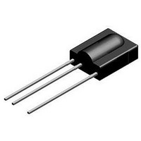
IR Receiver Module
Manufacturer
Vishay
Datasheet
1.TSOP31237.pdf
(9 pages)
Specifications of TSOP31237
Transmission Range
45m
Directivity
45°
Supply Voltage Range
2.5V To 5.5V
Opto Case Style
Through Hole
Operating Temperature Range
-25°C To +85°C
Carrier Frequency
36.7kHz
Supply Current
450µA
Lead Free Status / RoHS Status
Lead free / RoHS Compliant
Available stocks
Company
Part Number
Manufacturer
Quantity
Price


Typical Characteristics
Document Number 82217
Rev. 2, 19-May-03
VISHAY
V
V
V
E
O
OH
OL
V
V
V
e
16908
E
O
OH
OL
e
Optical Test Signal
(IR diode TSAL6200, I
Output Signal
Figure 2. Pulse Length and Sensitivity in Dark Ambient
t
d
1.0
0.9
0.8
0.7
0.6
0.5
0.4
0.3
0.2
0.1
0.0
1 )
Optical Test Signal
Output Signal, ( see Fig.4 )
0.1
600 ms
* t
pi
1 )
2 )
w 10/fo is recommended for optimal function
7/f
t
1.0
pi
0
–5/f
< t
T
E
Figure 1. Output Function
on
Figure 3. Output Function
optical test signal, fig.1
T = 60 ms
e
0
d
t
Output Pulse
t
– Irradiance ( mW/m
Input Burst Duration
po
pi
< t
10.0
< 15/f
F
2 )
*
po
= 0.4 A, 30 pulses, f = f
l = 950 nm,
T
< t
0
100.0 1000.010000.0
pi
+6/f
0
600 ms
(T
T
2
off
)
amb
0
, T = 10 ms)
= 25 °C unless otherwise specified)
94 8134
16110
t
t
t
t
16909
16925
16911
1.0
0.9
0.8
0.7
0.6
0.5
0.4
0.3
0.2
0.1
0.0
1.2
1.0
0.8
0.6
0.4
0.2
0.0
4.0
3.5
3.0
2.5
2.0
1.5
1.0
0.5
0.0
Figure 5. Frequency Dependence of Responsivity
0.1
0.01
0.7
Figure 6. Sensitivity in Bright Ambient
10W/m
Correlation with ambient light sources:
10W/m
E – Ambient DC Irradiance (W/m
1.0
Figure 4. Output Pulse Diagram
Ambient, l = 950 nm
0.10
E
2
f/f
^1.4klx (Std.illum.A,T=2855K)
optical test signal, fig.3
e
2
^8.2klx (Daylight,T=5900K)
– Irradiance ( mW/m
0
10.0
0.9
Df ( 3dB ) = f
– Relative Frequency
l = 950 nm,
f = f
Toff
Ton
1.00
Vishay Semiconductors
100.0 1000.010000.0
0
"5%
0
1.1
/10
10.00
TSOP312..
2
)
2
)
100.00
1.3
www.vishay.com
3
Related parts for TSOP31237
Image
Part Number
Description
Manufacturer
Datasheet
Request
R

Part Number:
Description:
357-036-542-201 CARDEDGE 36POS DL .156 BLK LOPRO
Manufacturer:
Vishay
Datasheet:
Part Number:
Description:
357-036-542-201 CARDEDGE 36POS DL .156 BLK LOPRO
Manufacturer:
Vishay
Datasheet:
Part Number:
Description:
357-036-542-201 CARDEDGE 36POS DL .156 BLK LOPRO
Manufacturer:
Vishay
Datasheet:
Part Number:
Description:
357-036-542-201 CARDEDGE 36POS DL .156 BLK LOPRO
Manufacturer:
Vishay
Datasheet:
Part Number:
Description:
357-036-542-201 CARDEDGE 36POS DL .156 BLK LOPRO
Manufacturer:
Vishay
Datasheet:
Part Number:
Description:
357-036-542-201 CARDEDGE 36POS DL .156 BLK LOPRO
Manufacturer:
Vishay
Datasheet:
Part Number:
Description:
357-036-542-201 CARDEDGE 36POS DL .156 BLK LOPRO
Manufacturer:
Vishay
Datasheet:
Part Number:
Description:
357-036-542-201 CARDEDGE 36POS DL .156 BLK LOPRO
Manufacturer:
Vishay
Datasheet:
Part Number:
Description:
357-036-542-201 CARDEDGE 36POS DL .156 BLK LOPRO
Manufacturer:
Vishay
Datasheet:
Part Number:
Description:
357-036-542-201 CARDEDGE 36POS DL .156 BLK LOPRO
Manufacturer:
Vishay
Datasheet:
Part Number:
Description:
357-036-542-201 CARDEDGE 36POS DL .156 BLK LOPRO
Manufacturer:
Vishay
Datasheet:
Part Number:
Description:
357-036-542-201 CARDEDGE 36POS DL .156 BLK LOPRO
Manufacturer:
Vishay
Datasheet:
Part Number:
Description:
357-036-542-201 CARDEDGE 36POS DL .156 BLK LOPRO
Manufacturer:
Vishay
Datasheet:
Part Number:
Description:
357-036-542-201 CARDEDGE 36POS DL .156 BLK LOPRO
Manufacturer:
Vishay
Datasheet:
Part Number:
Description:
357-036-542-201 CARDEDGE 36POS DL .156 BLK LOPRO
Manufacturer:
Vishay
Datasheet: