APW199D-R-24V IDEC, APW199D-R-24V Datasheet - Page 40
APW199D-R-24V
Manufacturer Part Number
APW199D-R-24V
Description
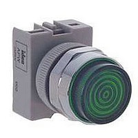
LED Panel Indicator
Manufacturer
IDEC
Datasheet
1.ASWHHY-B.pdf
(40 pages)
Specifications of APW199D-R-24V
Mounting Hole Dia
22mm
Led Color
Red
Forward Current If
11mA
Forward Voltage
24V
Supply Voltage
24V
Circuitry
SPDT
Actuator Diameter
22mm
Current Rating
11mA
Switch Operation
ON
Contact Current Max
10A
Lead Free Status / RoHS Status
Lead free / RoHS Compliant


Selector Switches
The operator shaft of each unit has a recess to identify in which direction to install the handle. Align the handle with the recess. Press color insert (TW-HC1)
into the handle and then press handle into the operator, as shown below.
.
Standard Operating Positions
Positions:
Non-illuminated 3-Position Operators
Installation
Installation of LED Illuminated Units
AC transformers are recommended for use in areas subjected to inductive noise. When using full voltage types, install a protection diode as shown below. (Diode
with DC power supply to protect against surges and noise.)
.
www.idec.com
Remove color insert before pulling out the handle.
Make sure that LED illuminated units are installed with
correct polarity, as indicated at the terminals.
Oiltight Switches & Pilot Devices
2-Position, 90°
1
Selector Switch
USA: (800) 262-IDEC or (408) 747-0550, Canada: (888) 317-IDEC
Lamp holder is installed
as shown, due to polarity.
Lead holder (used with two
stacks of contact blocks)
does not have polarity.
Illuminated
TW Pilot Lights
1
0
2
Make sure slot
is facing up
2
Recess
3-Position, 45°
1
Diode
Non-Illuminated
Selector Switch
Terminal
Instructions con’t
0
X1
Terminal X1 =
Positive
Terminal X2 =
Negative
1
2
1
4-Position, 45°
0
TW Illuminated Pushbuttons,
TW Selector Switches
(AC Transformer or Full Voltage)
2
Press in
LED
handle
2
Terminal
3
X2
4
1
5-Position, 30°
Press in
color insert
2
1
2
0
3
4
5
ø22mm - TW Series
A3-165
A3
Related parts for APW199D-R-24V
Image
Part Number
Description
Manufacturer
Datasheet
Request
R

Part Number:
Description:
APW199D-W-24V TW LED PL FV
Manufacturer:
IDEC
Datasheet:
Part Number:
Description:
INDICATOR, LED PANEL MNT, RED, 120V
Manufacturer:
IDEC
Datasheet:

Part Number:
Description:
INDICATOR, LED PANEL MNT, GREEN, 120V
Manufacturer:
IDEC
Datasheet:
Part Number:
Description:
INDICATOR, LED PANEL MNT, AMBER, 24V
Manufacturer:
IDEC
Datasheet:
Part Number:
Description:
Cable; Between IDEC MicroSmart (port 1 or 2) and HG2F/3F/4F; 5 ft.
Manufacturer:
IDEC Corporation
Datasheet:
Part Number:
Description:
Cable; Between IDEC Micro^3C/ONC/MicroSmart (port 2) PLCs and HG2F/3F/4F; 5 ft.
Manufacturer:
IDEC Corporation
Datasheet:
Part Number:
Description:
Angled Key for Idec HS6B Safety Switch
Manufacturer:
IDEC Corporation
Datasheet:
Part Number:
Description:
Accessory, L-Shaped Key for Idec HS5B and HS5E Safety Switch
Manufacturer:
IDEC Corporation
Datasheet:
Part Number:
Description:
Accessory, Straight Key for Idec HS5B and HS5E Safety Switch
Manufacturer:
IDEC Corporation
Datasheet:
Part Number:
Description:
Straight Key for Idec HS6B Safety Switch
Manufacturer:
IDEC Corporation
Datasheet:
Part Number:
Description:
INDICATOR INCANDESCENT LAMP, GREEN
Manufacturer:
IDEC
Datasheet:

Part Number:
Description:
LAMP, INDICATOR, INCAND, AMB
Manufacturer:
IDEC
Datasheet:
Part Number:
Description:
LAMP, INDICATOR, INCAND, GRN
Manufacturer:
IDEC
Datasheet:
Part Number:
Description:
LAMP, INDICATOR, INCAND, GRN
Manufacturer:
IDEC
Datasheet:
Part Number:
Description:
LAMP, INDICATOR, INCANDESCENT, RED
Manufacturer:
IDEC
Datasheet: