31-040.005 EAO, 31-040.005 Datasheet
31-040.005
Specifications of 31-040.005


Related parts for 31-040.005


31-040.005 Summary of contents
Page 1
... EAO – Your Expert Partner for Human Machine Interfaces EAO Product Information Series 31 ...
Page 2
...
Page 3
... Switches and Indicators 31 ...
Page 4
... Contents Description ...................................................................................................... 3 Product Assembly .......................................................................................... 4 Devices raised mounting ............................................................................... 5 Accessories..................................................................................................... 7 Technical Data............................................................................................... 12 Typical Applications ..................................................................................... 15 Application guidelines.................................................................................. 17 Marking .......................................................................................................... 18 Drawings........................................................................................................ 19 Index............................................................................................................... 27 2 06.2009 31 ...
Page 5
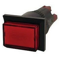
... Product Assembly Indicator round, raised mounting Illuminated pushbutton rectangular, raised mounting 06.2009 1 Lens 2 LED 3 Switch housing 4 Front plate 5 Fixing nut 1 Lens 2 LED 3 Switch housing 4 Front plate 5 Fixing nut 31 ...
Page 6
... The status of a maintained action switch can be determinded by the position of the lens. Specimen order 0 Indicator : - Indicator actuator mm, soldering terminal Essential accessories : - Lens plastic blue, transparent, flush Single-LED MG, 24 VAC/DC, blau 4 We reserve the right to modify technical data All dimensions 31-040.005 31-903.6 10-2J12.1066 3 06.2009 ...
Page 7
... Terminals Soldering terminal (also pluggable 2.8 x 0.5 mm Soldering terminal Mounting dimensions from page 20, Technical drawing from page 20, Circuit drawing from page Typ-Nr. Typ-Nr 31-703.006 31-701.006 31-704.006 31-702.006 - S 31-050.005 31-040.005 S1 31-050.002 31-040.002 UT 31-051.006 31-041.006 Front cap IP 40 Plastic black IP 40 Plastic black 31 Ø Typ-Nr 0.006 ...
Page 8
... 29 0.007 31-471.036 0.007 31-431.036 0.007 31-747.0292 0.008 31-743.0292 0.008 31-748.0292 0.008 31-744.0292 0.008 31-271.0252 0.006 31-271.022 0.006 31-131.0252 0.006 31-131.022 0.006 31-749.0292 0.010 31-745.0292 0.010 31-750.0292 0.010 31-746.0292 0.010 31-272.0252 0.008 31-132.0252 0.008 31-273.0252 0.010 31-133.0252 0.010 31-274.0252 0.012 31-134.0252 0.012 ...
Page 9
... 31-953.1 31-903.1 31-933.1 31-953.4 31-903.4 31-933.4 31-951.6 31-901.6 31-931.6 31-955.7 31-905.7 31-935.7 31-951.5 31-901.5 31-931.5 31-955.5 31-905.5 31-935.5 31-951.3 31-901.3 31-931.3 31-951.2 31-901.2 31-931.2 31-955.2 31-905.2 31-935.2 31-951.9 31-901.9 31-931.9 31-951.4 31-901.4 31-931.4 31-955.4 31-905.4 31-935.4 31-951.0 31-901.0 31-931.0 31-951.8 31-901.8 31-931 ...
Page 10
... Technical drawing from page 20 Blind plug Continuation see next page Blind plug Blind plug Plastic black Mounting dimensions from page 20 8 06.2009 Typ-Nr. Typ-Nr. 31-923 2 31-924.2 2 Typ-Nr. 01-927 01-926 Ø Typ-Nr. Typ-Nr. Typ-Nr. 01-948.0 01-947.0 01-949 0.003 4 0.003 e 2 0.011 1 0.011 e 1 0.001 ...
Page 11
... Universal terminal 2.8 x 0.5 mm for Plug-in terminal Insulation sleeve Continuation see next page Insulation sleeve Cover Plug-in terminals for snap-action switching element 2.8 mm for Flat receptacle 31-945 for Flat receptacle 31-946 Terminal cover Continuation see next page Terminal cover 31 e Typ-Nr ...
Page 12
... VAC/DC, 7/14 mA 10-2J13.1066 48 VAC/DC, 4/8 mA 10-2J19.1046 6 VDC 10-2J06.3146 12 VAC/DC, 4/7 mA 10-2J09.1065 24 VAC/DC, 4/7 mA 10-2J12.1065 28 VAC/DC, 4/7 mA 10-2J13.1065 48 VAC/DC, 2/4 mA 10-2J19.1045 6 VDC 10-2J06.3145 12 VAC/DC, 7/14 mA 10-2J09.1062 24 VAC/DC, 7/14 mA 10-2J12.1062 28 VAC/DC, 7/14 mA 10-2J13.1062 48 VAC/DC, 4/8 mA 10-2J19.1042 6 VDC 10-2J06.3142 12 VAC/DC, 7/14 mA 10-2J09.1069 24 VAC/DC, 7/14 mA 10-2J12.1069 28 VAC/DC, 7/14 mA 10-2J13 ...
Page 13
... Continuation see next page Dressing tool Operating voltage Typ-Nr. 230/240 V 02-904.7 110 V 02-904.0 125 V 02-904.1 145 V 02-904.3 Typ-Nr. 02-912.2 02-912.3 02-912.1 Typ-Nr. 02-905 Typ-Nr. 61-9740.0 Typ-Nr. 01-907 Typ-Nr. 01-906 31 e 0.003 0.003 0.003 0.003 e 0.045 0.090 0.025 e 0.011 e 0.003 e 0.020 e 0.030 11 06.2009 ...
Page 14
... Hz, amplitude 1.5 mm, as per IEC 60512-4-4, IEC 60068-2-6 Climate resistance Standard condition, as per IEC 60068-2-3 and 2-30 Changing condition, as per IEC 60068-2-14 and 2-33 Approvals Approbations CB (IEC 61058) CSA ENEC (EN 61058) Germanischer Lloyd UL Declaration of conformity CE 31 220 VDC 0.1 A ...
Page 15
... IP 65 with spray cover Shock resistance (Single impacts, semi-sinusoidal for 11 ms, as per IEC 60512-4-3, IEC 60068-2-27 Vibration resistance (sinusoidal 0-2000 Hz, amplitude 1.5 mm, as per IEC 60512-4-4, IEC 60068-2-6 Climate resistance Standard condition, as per IEC 60068-2-3 and 2-30 Changing condition, as per IEC 60068-2-14 and 2- 06.2009 ...
Page 16
... Technical Data > Buzzer Typ-Nr. 31-810.005 Switching system Buzzer system Electronic non-contacting buzzer with IC oscillator Material Alarm buzzer case Polyetherimide Front bezel Polyamide Mechanical characteristics Terminals Soldering terminal Electrical characteristics Frequency (tone) Approx. 2.8 kHz Interval frequency approx Sound pressure 88 dB (A) ± distance of 0.1 m Volume variable with a 1 MΩ ...
Page 17
... Typical Applications Diode element When indicators and illuminated pushbuttons equipped with diodes, the user is able to perform a lamp check or wire an alarm circuit simply with a considerable saving of space 06.2009 ...
Page 18
... Typical Applications > Buzzer (31-801.002) Depending on how terminals are connected, the buzzer can operate with a continous tone a(-) b(+) or with intermittent tone a(+) b(-). VDC > Buzzer (31-810.005 Supply voltage I 2. Supply voltage II Continuos tone Continous tone VAC VAC VDC VDC 16 06.2009 Intermittent tone Interval aprox ...
Page 19
... To get an efficient protection, the free-wheeling diode must be connected as close as possible to the inductive load! 0 Switching with inductive load Fig. 1 Switch + Free-wheeling Inductive VDC _ diode load Counter emf over load without free-wheeling diode Fig OFF 0 Sveral hundred to several thousend volts 06.2009 ...
Page 20
... abc abc 31 3. Film inserts Instead of using engraving the lenses can be fitted with transparent film inserts alternative. For this purpose, though advisible to use transparent lenses. In the case of use of a smoke-black lens the fitted film becomes readable only if the lamp is on. To insert the film, the feet of the lens holder have to be pushed together far enough to enable the lens to be lift off easily ...
Page 21
... M2 screw, if desired 12.7 3 PCB plug-in base page 9 3.81 3.81 Ø2.1 hole for central mounting + 0.1 with M2 screw, Ø1 desired all holes 4 Indicator actuator page 5 | Illuminated pushbutton actuator page 6 Terminals (rearside PCB layout (conductor side 06.2009 ...
Page 22
... Drawings Mounting dimensions 1 Indicator actuator page 5 | Buzzer page 5 | Illuminated pushbutton actuator page 6 | Blind plug page min. 2 Front protective cap page min. Technical drawing 1 Protective guard page Protective guard page 06.2009 Ø min. 18 min. 10 min. 31 ...
Page 23
... Drawings 3 Buzzer page 5 1.5 ... 6 10 Front protective cap page Protective cover page 14.5 6 Protective cover page 14.5 7 Indicator actuator page 1.5 ... Ø 06.2009 ...
Page 24
... Illuminated pushbutton actuator page 6 1.5 ... 6 L1 10.5 L Circuit drawing 1 Buzzer page Buzzer page Indicator actuator page 5 a-(x1) b+(x2) 4 Indicator actuator page 5 5 Illuminated pushbutton actuator page III 06.2009 Ø x1 x2 1NC+1NO 2NC+2NO 36 3NC+3NO 4NC+4NO 51 43.5 1NC+1NO 2NC+2NO 1NC, 1NO, 1NC+1NO, 2NC, 2NO 36 - ...
Page 25
... Illuminated pushbutton actuator page x1 III x2+ 7 Illuminated pushbutton actuator page 3(+) 4(-) 8 Illuminated pushbutton actuator page 3(+) 1(-) 4(-) 2(+) 9 Illuminated pushbutton actuator page x1 x2+ 10 Illuminated pushbutton actuator page Illuminated pushbutton actuator page 3(+) 4(-) 12 Illuminated pushbutton actuator page 3(+) 1(-) 4(-) 2(+) 13 Illuminated pushbutton actuator page x1 x2 06.2009 ...
Page 26
... Drawings 14 Illuminated pushbutton actuator page Illuminated pushbutton actuator page Illuminated pushbutton actuator page Illuminated pushbutton actuator page Illuminated pushbutton actuator page Illuminated pushbutton actuator page III Illuminated pushbutton actuator page x1 III x2+ 21 Illuminated pushbutton actuator page 3(+) 4(-) 24 06.2009 x2+ 31 ...
Page 27
... Illuminated pushbutton actuator page 3(+) 1(-) 4(-) 2(+) 23 Illuminated pushbutton actuator page x1 x2+ 24 Illuminated pushbutton actuator page x1 x2+ 25 Illuminated pushbutton actuator page 3(+) 4(-) 26 Illuminated pushbutton actuator page 3(+) 1(-) 4(-) 2(+) 27 Illuminated pushbutton actuator page x1 x2+ 28 Illuminated pushbutton actuator page Illuminated pushbutton actuator page 06.2009 ...
Page 28
... Drawings 30 Illuminated pushbutton actuator page Illuminated pushbutton actuator page Illuminated pushbutton actuator page Indicator actuator page 5 a-(x1) 3(+) b+(x2) 4(-) 34 Indicator actuator page 5 a-(x1) 3(+) 1(-) b+(x2) 4(-) 2(+) 26 06.2009 31 ...
Page 29
... Typ-Nr. Page 31-121.022 ................................... 6 31-121.0252 ................................. 6 31-122.0252 ................................. 6 31-123.0252 ................................. 6 31-124.0252 ................................. 6 31-131.022 ................................... 6 31-131.0252 ................................. 6 31-132.0252 ................................. 6 31-133.0252 ................................. 6 31-134.0252 ................................. 6 31-151.022 ................................... 6 31-151.0252 ................................. 6 31-152.0252 ................................. 6 31-153.0252 ................................. 6 31-154 ...
Page 30
... Typ-Nr. Page Typ-Nr ...
Page 31
...
Page 32
... E-mail sales.eit@eao.com Japan Phone +81 3 5444 5411 Fax +81 3 5444 0345 E-mail sales.esj@eao.com Netherlands Phone +31 78 653 17 00 Fax +31 78 653 17 99 E-mail sales.enl@eao.com Sweden Phone +46 8 683 86 60 Fax +46 8 724 29 12 E-mail sales.esw@eao.com Switzerland Phone +41 62 388 95 00 Fax ...