TORX147PL Toshiba, TORX147PL Datasheet - Page 3
TORX147PL
Manufacturer Part Number
TORX147PL
Description
RECEIVER, FIBRE OPTIC
Manufacturer
Toshiba
Datasheet
1.TORX147PL.pdf
(5 pages)
Specifications of TORX147PL
Connector Type
TosLink
Data Rate Max
15Mbps
Data Rate Min
0.1Mbps
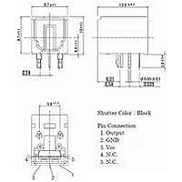
External Depth
13.5mm
External Length / Height
9.7mm
External Width
9.7mm
High Level Output Current
-2mA
High Level Output Voltage
2.5V
Data Transmission Distance
5m
Rohs Compliant
Yes
Lead Free Status / RoHS Status
Lead free / RoHS Compliant
Available stocks
Company
Part Number
Manufacturer
Quantity
Price
Company:

Part Number:
TORX147PL
Manufacturer:
SANYO
Quantity:
70
Part Number:
TORX147PL
Manufacturer:
TOSHIBA/东芝
Quantity:
20 000
Company:
Part Number:
TORX147PL(FT)
Manufacturer:
Toshiba
Quantity:
1 976


7. Board layout hole pattern
8. Precautions on Use
(1)
(2)
(3)
(4)
(5)
5.6 TYP.
2−φ1.7±0.05
Maximum rating
The maximum ratings are the limit values which must not be exceeded during operation of device.
None of these rating value must not be exceeded. If the maximum rating value is exceeded, the
characteristics of devices may never be restored properly. In extreme cases, the device may be
permanently damages.
Soldering
Optical modules are comprised of internal semiconductor devices. However, in principle, optical
modules are optical components. During soldering, ensure that flux does not contact with the emitting
surface or the detecting surface. Also ensure that proper flux removal is conducted after soldering.
Some optical modules come with shutter system. The shutter is closed to avoid malfunction when the
optical module is not in use. Note that it is not dust or waterproof.
As mentioned before, optical modules are optical components. Thus, in principle, soldering where
there may be flux residue and flux removal after soldering is not recommended. Toshiba recommend
that soldering be performed without the optical module mounted on the board. Then, after the board
has been cleaned, the optical module should be soldered on to the board manually.
If the optical module cannot be soldered manually, use non- halogen (chlorine- free) flux and make
sure, without cleaning, there is no residue such as chlorine. This is one of the ways to eliminate the
effects of flux. In such a cases, be sure to check the devices' reliability.
Noise resistance
It is believed that the use of optical transfer devices improve noise resistance. In theory, optical fiber
is not affected by noise at all. However, receiving modules which handle signals whose level is
extremely small, are susceptible to noise.
TOSLINK improve noise resistance to use a conductive case. However, the current signal output by
the optical receiving modules' photodiode is extremely small. Thus, in some environments, shielding
the case may not achieve sufficient noise resistance.
For systems which incorporate TOSLINK, Toshiba recommend testing using the actual device to
check its noise resistance.
Use a simple noise filter on TOSLINK fiber optic transceiving module's power line. If the ripple in the
power supply used is significant, reinforce the filter.
The optical module is to be used in an area which is susceptible to radiated noise, increase the
shielding by covering the optical module and the power line filter with a metallic cover.
Vibration and shock
This module is plastic sealed and has its wire fixed by resin. This structure is relatively resistant to
vibration and shock. In actual equipment, there are sometime cases in which vibration, shock, or
stress is applied to soldered parts or connected parts, resulting in lines cut. A care must be taken in
the design of equipment which will be subject to high levels of vibration.
Support pins
The TORX147PL(F,T) has support pins in order to fix itself to the PCB temporary. Please make the
hole for these pins in the PCB under the condition described in board layout hole pattern.
2.61 TYP.
(Recommendation)
2−φ1.1±0.05
3−φ0.8±0.05
2.625 TYP.
3
2.54 TYP.
2.54 TYP.
Unit:mm
Recommended PCB thickness:1.6mm
TORX147PL(F,T)
2004-02-02
Related parts for TORX147PL
Image
Part Number
Description
Manufacturer
Datasheet
Request
R

Part Number:
Description:
Toshiba Semiconductor [TOSHIBA IGBT Module Silicon N Channel IGBT]
Manufacturer:
TOSHIBA Semiconductor CORPORATION
Datasheet:
Part Number:
Description:
TOSHIBA GTR MODULE SILICON NPN TRIPLE DIFFUSED TYPE
Manufacturer:
TOSHIBA Semiconductor CORPORATION
Datasheet:
Part Number:
Description:
TOSHIBA GTR Module Silicon N Channel IGBT
Manufacturer:
TOSHIBA Semiconductor CORPORATION
Datasheet:
Part Number:
Description:
TOSHIBA Intelligent Power Module Silicon N Channel IGBT
Manufacturer:
TOSHIBA Semiconductor CORPORATION
Datasheet:
Part Number:
Description:
TOSHIBA INTELLIGENT POWER MODULE SILICON N CHANNEL LGBT
Manufacturer:
TOSHIBA Semiconductor CORPORATION
Datasheet:
Part Number:
Description:
TOSHIBA IGBT Module Silicon N Channel IGBT
Manufacturer:
TOSHIBA Semiconductor CORPORATION
Datasheet:
Part Number:
Description:
TOSHIBA GTR MODULE SILICON N−CHANNEL IGBT
Manufacturer:
TOSHIBA Semiconductor CORPORATION
Datasheet:
Part Number:
Description:
TOSHIBA Intelligent Power Module Silicon N Channel IGBT
Manufacturer:
TOSHIBA Semiconductor CORPORATION
Datasheet:
Part Number:
Description:
TOSHIBA GTR Module Silicon N Channel IGBT
Manufacturer:
TOSHIBA Semiconductor CORPORATION
Datasheet:
Part Number:
Description:
TOSHIBA INTELLIGENT POWER MODULE
Manufacturer:
TOSHIBA Semiconductor CORPORATION
Datasheet:
Part Number:
Description:
TOSHIBA Intelligent Power Module Silicon N Channel IGBT
Manufacturer:
TOSHIBA Semiconductor CORPORATION
Datasheet:
Part Number:
Description:
TOSHIBA Intelligent Power Module Silicon N Channel IGBT
Manufacturer:
TOSHIBA Semiconductor CORPORATION
Datasheet:
Part Number:
Description:
TOSHIBA IGBT Module Silicon N Channel IGBT
Manufacturer:
TOSHIBA Semiconductor CORPORATION
Datasheet:
Part Number:
Description:
TOSHIBA Intelligent Power Module Silicon N Channel IGBT
Manufacturer:
TOSHIBA Semiconductor CORPORATION
Datasheet:
Part Number:
Description:
Toshiba Semiconductor [SILICON N CHANNEL 1GBT]
Manufacturer:
TOSHIBA Semiconductor CORPORATION
Datasheet: