3560-16S Hirose Electric Co Ltd, 3560-16S Datasheet - Page 6
3560-16S
Manufacturer Part Number
3560-16S
Description
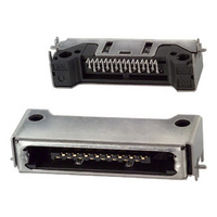
CONN RECEPTACLE 16 POS SMD
Manufacturer
Hirose Electric Co Ltd
Series
3500r
Datasheet
1.3540-16P-CV50.pdf
(6 pages)
Specifications of 3560-16S
Connector Type
Receptacle
Contact Type
Center Strip Contact
Number Of Positions
16
Number Of Positions Loaded
All
Pitch
0.031" (0.80mm)
Number Of Rows
1
Mounting Type
Surface Mount, Right Angle
Termination
Solder
Features
Board Lock
Contact Finish
Gold
Contact Finish Thickness
8µin (0.20µm)
Color
Black
Lead Free Status / RoHS Status
Contains lead / RoHS non-compliant
Row Spacing
-
Fastening Type
-
Other names
*3560-16S
H10018
H10018
Available stocks
Company
Part Number
Manufacturer
Quantity
Price

Company:
Part Number:
3560-16S(50)
Manufacturer:
HRS
Quantity:
100
Company:
Part Number:
3560-16S(61)
Manufacturer:
HRS
Quantity:
971


All non-RoHS products have been discontinued, or will be discontinued soon. Please check the products status on the Hirose website RoHS search at www.hirose-connectors.com, or contact your Hirose sales representative.
262
B B Technical DocumentⅡ Ⅱ
Connector Mounting Method
1. Soldering Method
2. Soldering and Screw Fastening Method
This connector and board mounting method uses soldering at the four dip locations marked A at the left and
right sides as well as the two surface mounting locations marked B at the left and right sides for a total of six
locations.
As illustrated in the diagram below, the opening portion of the connector is either inserted into the body of
the set or inserted into a rectangular hole of the set.
When there is not sufficient strength with the connector opening portion at the set, the mounting holes C (as
in Figure 1) at the left and right sides of the connector are used after the solder mounting to further fix the
connector with M2 screws.
The connector can be fixed to just the board with this method (as in Figure 2); however, in consideration of
connector twisting, the most effective mounting method is to fix the connector to both the body and the
board with screws as illustrated in Figures 3 and 4.
Location A represents board through holes of 1.8mm diameter and 1mm diameter, whereas
location B represents pads of 2.8 × 1.85mm width. (See the board mounting diagram.)
(Figure 2)
Board
Connector
(Figure 1)
(Figure 3)
Nut anchoring
Body of the set
Connector opening portion
(Figure 4)
Tapping screw anchoring
Board
04/2009
Related parts for 3560-16S
Image
Part Number
Description
Manufacturer
Datasheet
Request
R

Part Number:
Description:
CONN RECEPTACLE 10 POS REV SMD
Manufacturer:
Hirose Electric Co Ltd
Datasheet:
Part Number:
Description:
CONN RECEPTACLE 10 POS SMD
Manufacturer:
Hirose Electric Co Ltd
Datasheet:

Part Number:
Description:
CONN RECEPTACLE 16 POS SMD
Manufacturer:
Hirose Electric Co Ltd
Datasheet:
Part Number:
Description:
CONN RECEPTACLE 16 POS REV SMD
Manufacturer:
Hirose Electric Co Ltd
Datasheet:
Part Number:
Description:
CONN RECEPTACLE 16 POS REV SMD
Manufacturer:
Hirose Electric Co Ltd
Datasheet:

Part Number:
Description:
Conn Rectangular PL 14 POS 2.54mm Crimp RA Cable Mount
Manufacturer:
Hirose Electric Co Ltd
Part Number:
Description:
Conn Shrouded Header HDR 10 POS 2mm Solder ST SMD Embossed T/R
Manufacturer:
Hirose Electric Co Ltd
Datasheet:
Part Number:
Description:
DF11-20DP-2DSA(24)
Manufacturer:
Hirose Electric Co Ltd
Datasheet:
Part Number:
Description:
Conn Shrouded Header HDR 6 POS 2mm Solder ST Thru-Hole Bag
Manufacturer:
Hirose Electric Co Ltd
Datasheet:
Part Number:
Description:
Conn Shrouded Header HDR 8 POS 2mm Solder ST Thru-Hole Tube
Manufacturer:
Hirose Electric Co Ltd
Datasheet:
Part Number:
Description:
Conn Shrouded Header HDR 26 POS 2mm Solder ST SMD
Manufacturer:
Hirose Electric Co Ltd
Datasheet:
Part Number:
Description:
Conn Shrouded Header HDR 22 POS 2mm Solder ST SMD
Manufacturer:
Hirose Electric Co Ltd
Part Number:
Description:
Conn Shrouded Header HDR 22 POS 2mm Solder ST SMD
Manufacturer:
Hirose Electric Co Ltd
Part Number:
Description:
2mm 22w Wire to Board IDC Crimp Connector
Manufacturer:
Hirose Electric Co Ltd