AT-210TS-05D ALLIED TELESYN, AT-210TS-05D Datasheet - Page 2
AT-210TS-05D
Manufacturer Part Number
AT-210TS-05D
Description
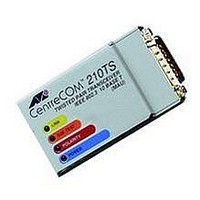
210TS-05 ETH TP MICRO XCVR W/4 LED SLIMLINE VER (MFG. ALLIED TELESYN)
Manufacturer
ALLIED TELESYN
Datasheet
1.AT-210TS-05D.pdf
(2 pages)


AT-MX10S, AT-MX20T & AT-210TS, Micro Transceivers
STATUS INDICATORS
AT-MX10S:
Power/HB
AT-MX20T:
Power
Transmit
Receive
Link
AT-210TS:
Power
Link
SQE Test
Polarity
AUI INTERFACE
Transmitter:
Threshold Voltage
SQE Test Delay
Duration
Collision Indication Delay 200ns
Assert Delay
Jabber Setup
Recovery
Receiver:
Start-Up Delay
Steady State Delay
Signal Amplitude
Loopback
Steady State Delay
Start-Up Delay
COAXIAL INTERFACE
Input Impedance
Coaxial Tap Capacitance < 6 pf
Input/Output Voltage:
DC Offset
AC Offset
Transmit Rise/Fall Time
TWISTED PAIR CONNECTOR (RJ-45)
Pin No.
1
2
3
4
5
6
7
8
(The Boiler-Plate copy below must appear on all datasheets)
USA Headquarters: 19800 North Creek Pkwy, Suite 200, Bothell, WA 98011, USA
European Headquarters: Via Motta 24, 6830 Chiasso, Switzerland
www.alliedtelesyn.com
© 2004 Allied Telesyn International Corp. All rights reserved. Information in this document is subject to change without notice.
All company names, logos, and product designs that are trademarks or registered trademarks are the property of their respective owners.
617-00151-00 Rev. C
Function
+TD
-TD
+RD
Not Used
Not Used
-RD
Not Used
Not Used
Two-color Heartbeat LED
Power is present from the DTE
Indicates packet is being transmitted to the media
Indicates packet is being received from the media
Indicates a valid link exists
Power is present from the DTE
Indicates a valid link exists
SQE/Heartbeat test enabled
Automatic polarity reversal has not occurred
Typical
-200mv
800ns
1000ns
200ns
45ms
450ms
500ns
100ns
±800mv
100ns
100ns
> 100K
Typical
-0.1v
1.86Vp-p
25ns
Range
-175 to -225mv
600 to 1600ns
500 to 1500ns
900ns
900ns
20 to 100ms
250 to 750ms
200ns
±550 to ±1200mv
500ns
Range
-0.5 to 0v
1.2 to 2.4Vp-p
±5ns
(European Sales)
TWISTED PAIR INTERFACE
Transmitter:
Peak Differential
Signal Amplitude
Transmitter Jitter
Harmonics Content
Common Mode Output Voltage
Start-Up Delay
Steady State Delay
Silence Voltage
Duration
Link Test Pulse
Output Impedance
Receiver:
Receiver Threshold
Input Impedance
Differential Noise Rejection 300mv
POWER CHARACTERISTICS
Isolation:
Breakdown Voltage
AT-MX10S
AT-MX20T/AT-210TS
Supply:
Voltage
Current
ENVIRONMENTAL SPECIFICATIONS
Operating Temp
Storage Temp.
Relative Humidity
PHYSICAL CHARACTERISTICS
Dimensions:
Standard
Slim-line
Weight:
Standard
Slim-line
ELECTRICAL/MECHANICAL APPROVALS
EMI
Safety
(Corporate)
Tel: 800.424.4284
Tel: (+41) 91 697.69.00
Tel: (+39) 02 414.112.1
Typical
2.5v
±1.5ns
27dB Down
100ns
100ns
±50mv
16ms
100ns
100
-400mv
100
500v rms 50/60Hz for 1 min
Typical
12v
300mA
0°C to 50°C
-20°C to 60°C
5% to 80% noncondensing
6.4cm x 4.6cm x 2.0cm
(2.5” x 1.8” x 0.8”)
6.9cm x 4.3cm x 2.5cm
(2.7” x 1.7” x 1.0”)
70g (2.4oz)
73g (2.5oz)
FCC Class A, TUV, Vfg-B
UL, CSA, TUV-GS
1500v rms 50/60 Hz for 1 min
Fax: 425.481.3895
Fax: (+41) 91 697.69.11
Fax: (+39) 02 414.112.61
Range
2.2 to 2.8v
±2ns
200ns
200ns
8 to 130ms
80 to 130ns
95 to 105
-350 to -450mv
95 to 105
Range
11.4 to 12.6v
500mA
ORDERING INFORMATION
AT -MX10S-05
10Base2 MAU slim-line transceiver
with slide latch
AT -MX20T -04
10T MAU transceiver with screw post
AT -MX20T -05
10T MAU transceiver with screw latch
AT -210TS-05D
10T MAU slim-line transceiver
with slide latch
AT -210TS-07D
10T MAU slim-line transceiver
with screw post
Related parts for AT-210TS-05D
Image
Part Number
Description
Manufacturer
Datasheet
Request
R

Part Number:
Description:
BUZZER PIEZO 15V 5.0KHZ PCB
Manufacturer:
PUI Audio, Inc.
Datasheet:

Part Number:
Description:
Antenna; Right Angle Telescoping Antenna, BNC Connector
Manufacturer:
BK Precision
Datasheet:

Part Number:
Description:
RF Bipolar Transistor
Manufacturer:
Avago Technologies US Inc.
Datasheet:

Part Number:
Description:
Attenuators 500-2000MHz IL 2.7dB Atten. Range 40dB
Manufacturer:
M/A-Com Technology Solutions

Part Number:
Description:
Switch Hardware INCANDESCENT 12V
Manufacturer:
NKK Switches
Datasheet:
Part Number:
Description:
24PT FETH MGD SWCH 2 GETH OR SFP UPLINKS
Manufacturer:
ALLIED TELESYN

Part Number:
Description:
100BTX TO 100BFX/ST MEDIA CONVRT
Manufacturer:
ALLIED TELESYN
Datasheet:
Part Number:
Description:
FS705LE 5PT 10/100 UNMGD SWCH EURO
Manufacturer:
ALLIED TELESYN
Part Number:
Description:
10/100 TO 10FL/100BSX ST AUTONEG MEDIA CONVRT
Manufacturer:
ALLIED TELESYN
Part Number:
Description:
16PT FETH MGD SWCH 1 GETH OR SFP UPLINK
Manufacturer:
ALLIED TELESYN
Part Number:
Description:
UPLINK MOD W/ GBIC BAY FOR RAPIER SWCH
Manufacturer:
ALLIED TELESYN
Part Number:
Description:
1PT 100FX MOD W/ MTG CONN FOR 8024M AND 8016F
Manufacturer:
ALLIED TELESYN
Part Number:
Description:
ALLIED TELESYN AT A45 NTWK ADPT GBIC 1000BFX
Manufacturer:
TECH DATA
Part Number:
Description:
1PT TRI-SPEED COPPER GETH MOD FOR 8024M 8016F
Manufacturer:
ALLIED TELESYN