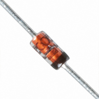
1N4148-TP Micro Commercial Components (MCC), 1N4148-TP Datasheet - Page 2

1N4148-TP
Manufacturer Part Number
1N4148-TP
Description
150mA, 75V Switching Diode, DO-35 / 13" REEL
Manufacturer
Micro Commercial Components (MCC)
Specifications of 1N4148-TP
Voltage - Forward (vf) (max) @ If
1V @ 10mA
Voltage - Dc Reverse (vr) (max)
75V
Current - Average Rectified (io)
150mA
Current - Reverse Leakage @ Vr
5µA @ 75V
Diode Type
Standard
Speed
Small Signal =< 200mA (Io), Any Speed
Reverse Recovery Time (trr)
4ns
Mounting Type
Through Hole
Package / Case
DO-204AH, DO-35, Axial
Product
Switching Diodes
Peak Reverse Voltage
75 V
Forward Continuous Current
0.15 A
Max Surge Current
2 A
Configuration
Single
Recovery Time
4 ns
Forward Voltage Drop
1 V
Maximum Reverse Leakage Current
5 uA
Maximum Operating Temperature
+ 175 C
Minimum Operating Temperature
- 65 C
Mounting Style
Through Hole
Capacitance, Junction
4 pF
Current, Forward
150 mA
Current, Reverse
50 μA
Current, Surge
2 A
Package Type
DO-35
Power Dissipation
500 mW
Primary Type
Schottky Barrier
Speed, Switching
Switching
Temperature, Junction, Maximum
+175 °C
Temperature, Operating
-65 to +175 °C
Time, Recovery
4 ns
Voltage, Forward
1 V
Voltage, Reverse
75 V
Forward Current If(av)
150mA
Repetitive Reverse Voltage Vrrm Max
100V
Forward Voltage Vf Max
1V
Reverse Recovery Time Trr Max
4µs
Forward Surge Current Ifsm Max
2A
Rohs Compliant
Yes
Lead Free Status / RoHS Status
Lead free / RoHS Compliant
Capacitance @ Vr, F
-
Lead Free Status / Rohs Status
RoHS Compliant part
Other names
1N4148-TPMSTR
Revision: A
MilliAmps
1N4148
.04
.01
.02
.06
10
20
.2
.4
.1
.6
6
2
4
1
Figure 1
Typical Forward Characteristics
Instantaneous Forward Current - MilliAmperes versus
Instantaneous Forward Voltage - Volts
pF
.4
10
Figure 3
Junction Capacitance
.4
.2
.1
4
6
1
2
.6
.1
.6
25°C
.2
www.mccsemi.com
.8
.4
Volts
1.0
T
Volts
J
=25°C
1
1.2
Junction Capacitance - pF versus
Reverse Voltage - Volts
2
1.4
4
2 of 4
10
MilliWatts
20
600
200
100
500
400
300
40
0
Admissable Power Dissipation - MilliWatts versus
Junction Temperature - °C
0
Figure 2
Power Dissipation Derating Curve
Single Phase, Half Wave
60Hz Resistive or Inductive Load
50
100 200
75
Micro Commercial Components
400
M C C
100
°C
125
1000
150
2011/01/01
175
TM


