VS-70HFR20 Vishay, VS-70HFR20 Datasheet - Page 3
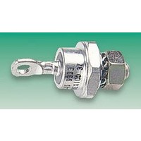
VS-70HFR20
Manufacturer Part Number
VS-70HFR20
Description
DIODE, STANDARD, 70A, 200V
Manufacturer
Vishay
Datasheet
1.VS-70HF20.pdf
(7 pages)
Specifications of VS-70HFR20
Diode Type
Standard Recovery
Repetitive Reverse Voltage Vrrm Max
200V
Forward Current If(av)
70A
Forward Voltage Vf Max
1.35V
Forward Surge Current Ifsm Max
1.2kA
Operating Temperature Range
-65°C To
Lead Free Status / RoHS Status
Lead free / RoHS Compliant


www.irf.com
Thermal and Mechanical Specifications
(The following table shows the increment of thermal resistence R
Ordering Information Table
T
T
R
R
T
wt
R
J
stg
Conduction angle
thCS
thJC
thJC
Conduction
Parameter
Max. junction operating temperature range
Max. storage temperature range
Max. thermal resistance, junction to case
Max. thermal resistance, case
to heatsink
Max. allowed mounting torque ±10%
Approximate weight
Case style
180°
120°
90°
60°
30°
1
2
3
4
5
-
-
-
-
-
70 = Standard device
71 = Not isolated lead
72 = Isolated lead with silicone sleeve
HF
HA
None = Stud Normal Polarity (Cathode to Stud)
R
Voltage code: Code x 10 = V
None = Stud base DO-203AB (DO-5) 1/4" 28UNF-2A
M
Sinusoidal conduction Rectangular conduction Units
(Red = Reverse polarity)
(Blue = Normal polarity)
= Standard diode
= Avalanche diode
= Stud Reverse Polarity (Anode to Stud)
= Stud base DO-203AB (DO-5) M6 X 1 - (Not available for Avalanche diodes)
Device Code
0.08
0.10
0.13
0.19
0.30
RRM
70
-65 to 180
-65 to 180
1
10 to 120
(See Voltage Ratings table)
HF
thJC
2
70HF(R)
DO-203AB (DO5)
2.3 - 3.4
17 (0.6)
20 - 30
0.06
0.11
0.14
0.20
0.30
0.25
when devices operate at different conduction angles than DC)
0.45
140 to 160
R
-65 to 150
-65 to 150
3
160
4
K/W
Units
M
K/W
lbf
g (oz)
5
°C
Nm
·
in
Conditions
Conditions
DC operation
Mounting surface, smooth, flat and
greased
Not lubricated threads
See Outline Table
T
J
= T
Bulletin I20202 rev. A 05/98
J
max.
70HF(R) Series
3
Related parts for VS-70HFR20
Image
Part Number
Description
Manufacturer
Datasheet
Request
R

Part Number:
Description:
Vs-240-7.5 Metal Enclosed Switching Power Supply
Manufacturer:
CUI INC
Datasheet:

Part Number:
Description:
VCSO Oscillators 698.81MHz to 794.72M 3.3Volt -40 to 85C
Manufacturer:
Vectron
Datasheet:
Part Number:
Description:
VCSO Oscillators 622.08Mhz to 669.32M 3.3Volt -40 to 85C
Manufacturer:
Vectron
Datasheet:
Part Number:
Description:
VCSO Oscillators 622.08MHz to 644.53M 3.3Volt -40 to 85C
Manufacturer:
Vectron
Datasheet:
Part Number:
Description:
VCSO Oscillators 644.53MHz to 693.48M 3.3Volt -40 to 85C
Manufacturer:
Vectron
Datasheet:
Part Number:
Description:
VCSO Oscillators 669.32MHz to 693.48M 3.3Volt -40 to 85C
Manufacturer:
Vectron
Datasheet:
Part Number:
Description:
VCSO Oscillators 672.16MHz to 696.61M 3.3Volt -40 to 85C
Manufacturer:
Vectron
Datasheet:
Part Number:
Description:
VCSO Oscillators 622.08MHz to 672.16M 3.3Volt -40 to 85C
Manufacturer:
Vectron
Datasheet:
Part Number:
Description:
VCSO Oscillators 657.42MHz to 707.35M 3.3Volt -40 to 85C
Manufacturer:
Vectron
Datasheet:

Part Number:
Description:
SCHOTTKY RECTIFIER, CMN CTHD, 7A, D-PAK
Manufacturer:
Vishay
Datasheet:

Part Number:
Description:
Schottky (Diodes & Rectifiers) 7.0 Amp 60 Volt Common Cathode
Manufacturer:
Vishay
Datasheet:

Part Number:
Description:
Manufacturer:
Phoenix Contact
Datasheet:
Part Number:
Description:
Open Frame Power Supply
Manufacturer:
CUI [CUI INC]
Datasheet:

Part Number:
Description:
RECTIFIER DIODES,COMMON CATHODE,SCHOTTKY,100V V(RRM),TO-252AA
Manufacturer:
Vishay
Datasheet:
Part Number:
Description:
RECTIFIER DIODES,COMMON CATHODE,SCHOTTKY,100V V(RRM),TO-252AA
Manufacturer:
Vishay
Datasheet: