VS-22RIA100 Vishay, VS-22RIA100 Datasheet
VS-22RIA100
Specifications of VS-22RIA100


Related parts for VS-22RIA100


VS-22RIA100 Summary of contents
Page 1
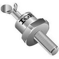
MEDIUM POWER THYRISTORS Features Improved glass passivation for high reliability and exceptional stability at high temperature High di/dt and dv/dt capabilities Standard package Low thermal resistance Metric threads version available Types up to 1600V DRM RRM Typical ...
Page 2
Series Bulletin I2403 rev. A 07/00 ELECTRICAL SPECIFICATIONS Voltage Ratings Voltage V /V DRM RRM Type number Code peak and off-state voltage ( 22RIA 80 100 120 140 160 (1) Units may be broken over ...
Page 3
Switching Parameter di/dt Max. rate of rise of turned-on current V 600V DRM V 800V DRM V 1000V DRM V 1600V DRM t Typical turn-on time gt t Typical reverse recovery time rr t Typical turn-off time q (*) t ...
Page 4
Series Bulletin I2403 rev. A 07/00 Thermal and Mechanical Specification Parameter T Max. operating temperature range J T Max. storage temperature range stg R Max. thermal resistance, thJC junction to case R Max. thermal resistance, thCS case to heatsink ...
Page 5
Outline Table 130 22RIA Series (100 to 1200V) R (DC) = 0.86 K/W thJC 120 110 Conduction Angle 100 30° 60° 90° 120° Average On-state Current (A) Fig Current Ratings Characteristic www.irf.com ...
Page 6
Series Bulletin I2403 rev. A 07/00 40 180° 35 120° 90° 30 60° 30° 25 RMS Limit Average On-state Current (A) Fig On-state Power Loss Characteristics ...
Page 7
Fig Forward Voltage Drop Characteristics 130 22RIA Series (1400 to 1600V) R (DC) = 0.86 K/W thJC 120 110 Conduction Angle 30° 100 60° 90° 120° Average ...
Page 8
Series Bulletin I2403 rev. A 07/ 180° 45 120° 90° 40 60° 35 30° 30 RMS Limit 22RIA Series 10 (1400 to 1600V 125° ...
Page 9
Steady State Value R = 0.86 K/W thJC (DC Operation) 0.1 0.01 0.001 0.01 Fig Thermal Impedance Z 100 Rectangular gate pulse a) Recommended load line for rated di/dt : 10V, 20ohms tr <=0.5 µs, tp >= ...