VSKT250-16 Vishay, VSKT250-16 Datasheet - Page 3
VSKT250-16
Manufacturer Part Number
VSKT250-16
Description
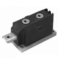
SCR THYRISTOR, 250A 1.6KV ADD-A-PAK
Manufacturer
Vishay
Specifications of VSKT250-16
Peak Repetitive Off-state Voltage, Vdrm
1.6kV
Current It Av
250A
Peak Non Rep Surge Current Itsm 50hz
8.9kA
Operating Temperature Range
-40°C To +125°C
Thyristor Case
ADD-A-Pak
No. Of Pins
7
Structure
Series Connection - All SCRs
Number Of Scrs, Diodes
2 SCRs
Voltage - Off State
1600V
Current - Gate Trigger (igt) (max)
200mA
Current - On State (it (av)) (max)
250A
Current - On State (it (rms)) (max)
555A
Current - Non Rep. Surge 50, 60hz (itsm)
8500A, 8900A
Current - Hold (ih) (max)
500mA
Mounting Type
Chassis Mount
Package / Case
3-MAGN-A-PAK™
Rated Repetitive Off-state Voltage Vdrm
1600 V
Off-state Leakage Current @ Vdrm Idrm
50 mA
Holding Current (ih Max)
500 mA
Maximum Operating Temperature
+ 130 C
Minimum Operating Temperature
- 40 C
Mounting Style
Screw
Breakover Current Ibo Max
8900 A
Gate Trigger Current (igt)
200 mA
Gate Trigger Voltage (vgt)
3 V
Maximum Gate Peak Inverse Voltage
5 V
Repetitive Peak Forward Blocking Voltage
1600 V
Lead Free Status / RoHS Status
Lead free / RoHS Compliant
Lead Free Status / RoHS Status
Lead free / RoHS Compliant, Contains lead / RoHS non-compliant
Other names
*IRKT250-16
IRKT250-16
IRKT250-16
IRKT250-16
IRKT250-16


Note
• The table above shows the increment of thermal resistance R
Document Number: 93581
Revision: 02-Jul-10
THERMAL AND MECHANICAL SPECIFICATIONS
PARAMETER
Maximum junction operating and storage
temperature range
Maximum thermal resistance,
junction to case per junction
Maximum resistance, case to heatsink
per module
Mounting torque
± 10 %
Approximate weight
Case style
R CONDUCTION PER JUNCTION
DEVICE
VSK.250
VSK.270
VSK.320
0.009
0.008
0.008
180°
MAP to heatsink
busbar to MAP
DiodesAmericas@vishay.com, DiodesAsia@vishay.com,
For technical questions within your region, please contact one of the following:
SINUSOIDAL CONDUCTION
Standard Recovery Diodes, 250 A to 320 A
0.010
0.012
0.010
120°
AT T
(MAGN-A-PAK Power Modules)
J
0.014
0.014
0.013
MAXIMUM
90°
SYMBOL
T
R
R
J
, T
thJC
thCS
Stg
0.020
0.020
0.020
60°
DC operation
Mounting surface flat, smooth and
greased
A mounting compound is recommended
and the torque should be rechecked
after a period of about 3 hours to allow for
the spread of the compound.
0.032
0.032
0.032
thJC
30°
TEST CONDITIONS
when devices operate at different conduction angles than DC
VSK.250, VSK.270, VSK.320 Series
0.007
0.007
0.007
180°
RECTANGULAR CONDUCTION
0.011
0.011
0.011
120°
DiodesEurope@vishay.com
AT T
J
0.015
0.015
0.015
MAXIMUM
90°
Vishay Semiconductors
VSK.250 VSK.270 VSK.320
0.16
0.021
0.020
0.020
60°
- 40 to 150
VALUES
8 to 10
4 to 6
MAGN-A-PAK
0.035
800
0.033
0.033
0.033
30
30°
0.125
www.vishay.com
UNITS
K/W
UNITS
K/W
Nm
oz.
°C
g
3
Related parts for VSKT250-16
Image
Part Number
Description
Manufacturer
Datasheet
Request
R

Part Number:
Description:
SCR DBL HISCR 400V 230A MAGNAPAK
Manufacturer:
Vishay
Datasheet:
Part Number:
Description:
SCR DBL HISCR 800V 230A MAGNAPAK
Manufacturer:
Vishay
Datasheet:
Part Number:
Description:
SCR DBL HISCR 1200V 230A MAGNPAK
Manufacturer:
Vishay
Datasheet:
Part Number:
Description:
SCR DBL HISCR 1400V 230A MAGNPAK
Manufacturer:
Vishay
Datasheet:

Part Number:
Description:
SCR Modules 250 Amp 1600 Volt 550 Amp IT(RMS)
Manufacturer:
Vishay
Datasheet:

Part Number:
Description:
STANDARD RECOVERY DIODES, 250 TO 320 A (MAGN-A-PAK POWER MODULES)
Manufacturer:
Vishay
Part Number:
Description:
SCR Modules 250 Amp 1400 Volt 550 Amp IT(RMS)
Manufacturer:
Vishay
Part Number:
Description:
SCR Modules 250 Amp 800 Volt 550 Amp IT(RMS)
Manufacturer:
Vishay
Datasheet:
Part Number:
Description:
SCR Modules 250 Amp 400 Volt 550 Amp IT(RMS)
Manufacturer:
Vishay
Part Number:
Description:
357-036-542-201 CARDEDGE 36POS DL .156 BLK LOPRO
Manufacturer:
Vishay
Datasheet:
Part Number:
Description:
357-036-542-201 CARDEDGE 36POS DL .156 BLK LOPRO
Manufacturer:
Vishay
Datasheet:
Part Number:
Description:
357-036-542-201 CARDEDGE 36POS DL .156 BLK LOPRO
Manufacturer:
Vishay
Datasheet:
Part Number:
Description:
357-036-542-201 CARDEDGE 36POS DL .156 BLK LOPRO
Manufacturer:
Vishay
Datasheet:
Part Number:
Description:
357-036-542-201 CARDEDGE 36POS DL .156 BLK LOPRO
Manufacturer:
Vishay
Datasheet: