40HFR20 Vishay, 40HFR20 Datasheet - Page 3
40HFR20
Manufacturer Part Number
40HFR20
Description
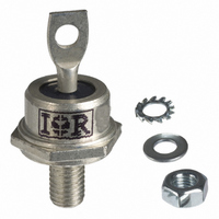
STANDARD DIODE, 40A, 200V, DO-5
Manufacturer
Vishay
Datasheet
1.40HF60.pdf
(7 pages)
Specifications of 40HFR20
Repetitive Reverse Voltage Vrrm Max
200V
Forward Current If(av)
40A
Forward Voltage Vf Max
1.3V
Forward Surge Current Ifsm Max
595A
Diode Type
Standard Recovery
Voltage - Forward (vf) (max) @ If
1.3V @ 125A
Voltage - Dc Reverse (vr) (max)
200V
Current - Average Rectified (io)
40A
Current - Reverse Leakage @ Vr
9mA @ 200V
Speed
Standard Recovery >500ns, > 200mA (Io)
Mounting Type
Chassis, Stud Mount
Package / Case
DO-203AB, DO-5, Stud
Product
Standard Recovery Rectifier
Configuration
Single
Reverse Voltage
200 V
Forward Voltage Drop
1.3 V at 125 A
Forward Continuous Current
40 A
Max Surge Current
595 A
Reverse Current Ir
9000 uA
Mounting Style
Stud
Lead Free Status / RoHS Status
Lead free / RoHS Compliant
Reverse Recovery Time (trr)
-
Capacitance @ Vr, F
-
Lead Free Status / RoHS Status
Lead free / RoHS Compliant, Lead free / RoHS Compliant
Other names
*40HFR20
VS-40HFR20
VS-40HFR20
VS40HFR20
VS40HFR20
VS-40HFR20
VS-40HFR20
VS40HFR20
VS40HFR20


Note
•
Document Number: 93513
Revision: 25-May-09
ΔR
CONDUCTION ANGLE
The table above shows the increment of thermal resistance R
thJC
CONDUCTION
180°
120°
90°
60°
30°
190
180
170
160
150
140
130
190
180
170
160
150
140
130
120
Fig. 1 - Current Ratings Characteristics
Fig. 2 - Current Ratings Characteristics
0
0
5 10 15 20 25 30 35 40 45
10
30°
40HF(R) Series (100V to 1200V)
Average Forward Current (A)
Average Forward Current (A)
40HF(R) Series (100V to 1200V)
20
60°
30°
SINUSOIDAL CONDUCTION
90°
30
60°
120°
40
Conduction Period
Conduction Angle
90°
180°
For technical questions, contact:
0.14
0.16
0.21
0.30
0.50
50
120°
DC
60
Standard Recovery Diodes,
180°
70
(Stud Version), 40 A
RECTANGULAR CONDUCTION
thJC
when devices operate at different conduction angles than DC
ind-modules@vishay.com
0.10
0.17
0.22
0.31
0.50
160
150
140
130
120
110
100
160
150
140
130
120
110
100
90
80
Vishay High Power Products
Fig. 4 - Current Ratings Characteristics
0
0
Fig. 3 - Current Ratings Characteristics
5 10 15 20 25 30 35 40 45
10
40HF(R) Series (1400V, 1600V)
30°
Average Forward Current (A)
Average Forward Current (A)
40HF(R) Series (1400V, 1600V)
TEST CONDITIONS
20
60°
T
J
30°
= T
90°
30
40HF(R) Series
J
120°
60°
maximum
40
Conduction Period
Conduction Angle
180°
90°
50
120°
DC
60
180°
www.vishay.com
70
UNITS
K/W
3
Related parts for 40HFR20
Image
Part Number
Description
Manufacturer
Datasheet
Request
R

Part Number:
Description:
THYRISTOR, 235A, 600V, TO-209AB
Manufacturer:
Powerex Inc
Datasheet:

Part Number:
Description:
DIODE SCHOTTKY 10A 100V SMPC
Manufacturer:
Vishay
Datasheet:

Part Number:
Description:
357-036-542-201 CARDEDGE 36POS DL .156 BLK LOPRO
Manufacturer:
Vishay
Datasheet:
Part Number:
Description:
357-036-542-201 CARDEDGE 36POS DL .156 BLK LOPRO
Manufacturer:
Vishay
Datasheet:
Part Number:
Description:
357-036-542-201 CARDEDGE 36POS DL .156 BLK LOPRO
Manufacturer:
Vishay
Datasheet:
Part Number:
Description:
357-036-542-201 CARDEDGE 36POS DL .156 BLK LOPRO
Manufacturer:
Vishay
Datasheet:
Part Number:
Description:
357-036-542-201 CARDEDGE 36POS DL .156 BLK LOPRO
Manufacturer:
Vishay
Datasheet:
Part Number:
Description:
357-036-542-201 CARDEDGE 36POS DL .156 BLK LOPRO
Manufacturer:
Vishay
Datasheet:
Part Number:
Description:
357-036-542-201 CARDEDGE 36POS DL .156 BLK LOPRO
Manufacturer:
Vishay
Datasheet:
Part Number:
Description:
357-036-542-201 CARDEDGE 36POS DL .156 BLK LOPRO
Manufacturer:
Vishay
Datasheet:
Part Number:
Description:
357-036-542-201 CARDEDGE 36POS DL .156 BLK LOPRO
Manufacturer:
Vishay
Datasheet:
Part Number:
Description:
357-036-542-201 CARDEDGE 36POS DL .156 BLK LOPRO
Manufacturer:
Vishay
Datasheet:
Part Number:
Description:
357-036-542-201 CARDEDGE 36POS DL .156 BLK LOPRO
Manufacturer:
Vishay
Datasheet:
Part Number:
Description:
357-036-542-201 CARDEDGE 36POS DL .156 BLK LOPRO
Manufacturer:
Vishay
Datasheet:
Part Number:
Description:
357-036-542-201 CARDEDGE 36POS DL .156 BLK LOPRO
Manufacturer:
Vishay
Datasheet: