VS-MBR4045WTPBF Vishay, VS-MBR4045WTPBF Datasheet - Page 2
VS-MBR4045WTPBF
Manufacturer Part Number
VS-MBR4045WTPBF
Description
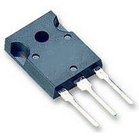
DIODE, SCHOTTKY, 40A, 45V, TO-247AC
Manufacturer
Vishay
Datasheet
1.VS-MBR4045WTPBF.pdf
(7 pages)
Specifications of VS-MBR4045WTPBF
Repetitive Reverse Voltage Vrrm Max
45V
Forward Current If(av)
40A
Forward Voltage Vf Max
590mV
Forward Surge Current Ifsm Max
1.02kA
Operating Temperature Range
-55°C To
Diode Type
Schottky
Lead Free Status / RoHS Status
Lead free / RoHS Compliant
Available stocks
Company
Part Number
Manufacturer
Quantity
Price


Bulletin PD-20677 rev. B 11/06
Absolute Maximum Ratings
Thermal-Mechanical Specifications
2
MBR4045WTPbF
Voltage Ratings
Electrical Specifications
I
I
I
E
I
T
T
R
R
wt
T
V
I
V
r
C
L
dv/dt Max. Voltage Rate of Change
V
V
F(AV)
FRM
FSM
AR
RM
t
S
J
AS
T
stg
FM
F(TO)
thJC
thCS
R
RWM
Parameters
Parameters
Part number
Max. DC Reverse Voltage (V)
Max. Working Peak Reverse Voltage (V)
Max. Average Forward
Current
Peak Repetitive Forward
Current
Max.Peak One Cycle Non-Repetitive
Surge Current ( Per Leg) See fig.7
Non-Repetitive Avalanche Energy
Repetitive Avalanche Current
Max. Forward Voltage Drop
Max. Instantaneus Reverse Current
Threshold Voltage
Forward Slope Resistance
Max. Junction Capacitance
Typical Series Inductance
Max. Junction Temperature Range
Max. Storage Temperature Range
Max. Thermal Resistance
Junction to Case (Per Package)
Typical Thermal Resistance
Case to Heatsink
Approximate Weight
Mounting Torque
Case Style
Device Marking
Parameters
(1)
(1)
(Per Leg)
(Per Device)
(Per Leg)
(Per Leg)
(Per Leg)
Min.
Max.
TO-247AC (TO-3P)
-55 to 150
-55 to 175
Values
Values
6 (0.21)
10000
12 (10)
MBR4045WT
0.59
0.78
0.56
0.72
1.75
0.29
10.3
Values Units
6 (5)
900
7.5
50
85
1.4
0.7
1020
265
20
40
40
20
3
Kg-cm
Units
(Ibf-in)
g (oz.)
Units
V/ μs
°C/W DC operation
°C/W Mounting surface, smooth and greased
mA
mA
mA
mΩ
mJ
nH
pF
°C
°C
A
A
A
V
V
V
V
V
A
JEDEC
@ T
T
5μs Sine or 3μs Rect. pulse
10ms Sine or 6ms Rect. pulse
T
Current decaying linearly to zero in 1 μsec
Frequency limited by T
Rated V
@ 20A
@ 40A
@ 20A
@ 40A
T
T
T
T
V
Measured from top of terminal to mounting plane
(Rated V
J
C
J
J
J
J
R
= 25 °C, I
= 25 °C
= 100 °C
= 125 °C
= 125° C
= T
= 5V
C
= 125°C, 50% duty cycle, rectangular waveform
J
max.
DC
R
R
, square wave, 20kHz
)
Conditions
Conditions
Conditions
(test signal range 100Khz to 1Mhz) 25°C
AS
MBR4045WTPbF
T
T
Rated DC voltage
= 3 Amps, L = 4.40 mH
(1) Pulse Width < 300μs, Duty Cycle <2%
J
J
= 25 °C
= 125 °C
45
J
max. V
Following any rated
load condition and with
rated V
A
= 1.5 x V
www.irf.com
RRM
R
typical
applied
Related parts for VS-MBR4045WTPBF
Image
Part Number
Description
Manufacturer
Datasheet
Request
R

Part Number:
Description:
357-036-542-201 CARDEDGE 36POS DL .156 BLK LOPRO
Manufacturer:
Vishay
Datasheet:
Part Number:
Description:
357-036-542-201 CARDEDGE 36POS DL .156 BLK LOPRO
Manufacturer:
Vishay
Datasheet:
Part Number:
Description:
357-036-542-201 CARDEDGE 36POS DL .156 BLK LOPRO
Manufacturer:
Vishay
Datasheet:
Part Number:
Description:
357-036-542-201 CARDEDGE 36POS DL .156 BLK LOPRO
Manufacturer:
Vishay
Datasheet:
Part Number:
Description:
357-036-542-201 CARDEDGE 36POS DL .156 BLK LOPRO
Manufacturer:
Vishay
Datasheet:
Part Number:
Description:
357-036-542-201 CARDEDGE 36POS DL .156 BLK LOPRO
Manufacturer:
Vishay
Datasheet:
Part Number:
Description:
357-036-542-201 CARDEDGE 36POS DL .156 BLK LOPRO
Manufacturer:
Vishay
Datasheet:
Part Number:
Description:
357-036-542-201 CARDEDGE 36POS DL .156 BLK LOPRO
Manufacturer:
Vishay
Datasheet:
Part Number:
Description:
357-036-542-201 CARDEDGE 36POS DL .156 BLK LOPRO
Manufacturer:
Vishay
Datasheet:
Part Number:
Description:
357-036-542-201 CARDEDGE 36POS DL .156 BLK LOPRO
Manufacturer:
Vishay
Datasheet:
Part Number:
Description:
357-036-542-201 CARDEDGE 36POS DL .156 BLK LOPRO
Manufacturer:
Vishay
Datasheet:
Part Number:
Description:
357-036-542-201 CARDEDGE 36POS DL .156 BLK LOPRO
Manufacturer:
Vishay
Datasheet:
Part Number:
Description:
357-036-542-201 CARDEDGE 36POS DL .156 BLK LOPRO
Manufacturer:
Vishay
Datasheet:
Part Number:
Description:
357-036-542-201 CARDEDGE 36POS DL .156 BLK LOPRO
Manufacturer:
Vishay
Datasheet:
Part Number:
Description:
357-036-542-201 CARDEDGE 36POS DL .156 BLK LOPRO
Manufacturer:
Vishay
Datasheet: