VS-MBR1035PBF Vishay, VS-MBR1035PBF Datasheet - Page 2
VS-MBR1035PBF
Manufacturer Part Number
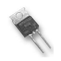
VS-MBR1035PBF
Description
DIODE, SCHOTTKY, 10A, 35V, TO-220AC
Manufacturer
Vishay
Datasheet
1.VS-MBR1035PBF.pdf
(7 pages)
Specifications of VS-MBR1035PBF
Repetitive Reverse Voltage Vrrm Max
35V
Forward Current If(av)
10A
Forward Voltage Vf Max
840mV
Forward Surge Current Ifsm Max
1.06kA
Operating Temperature Range
-65°C To
Diode Type
Schottky
Lead Free Status / RoHS Status
Lead free / RoHS Compliant
Available stocks
Company
Part Number
Manufacturer
Quantity
Price


Bulletin PD-20863 rev. A 04/06
Voltage Ratings
Thermal-Mechanical Specifications
MBR10..PbF Series
2
Absolute Maximum Ratings
Electrical Specifications
V
V
I
I
I
E
I
V
I
V
r
C
L
dv/dt Max. Voltage Rate of Change
T
T
R
R
wt
T
F(AV)
FRM
FSM
AR
RM
t
S
R
RWM
AS
FM
F(TO)
J
stg
T
thJC
thCS
Part number
Max. DC Reverse Voltage (V)
Max. Working Peak Reverse Voltage (V)
Parameters
Max. Average Forward Current
Peak Repetitive Forward
Current
Non Repetitive Peak
Surge Current
Non-Repetitive Avalanche Energy
Repetitive Avalanche Current
Max. Forward Voltage Drop
Max. Instantaneus Reverse Current
Threshold Voltage
Forward Slope Resistance
Max. Junction Capacitance
Typical Series Inductance
(Rated V
Parameters
Parameters
Max. Junction Temperature Range
Max. Storage Temperature Range
Max. Thermal Resistance
Junction to Case
Typical Thermal Resistance
Case to Heatsink
Approximate Weight
Mounting Torque
Marking Device
R
)
(1)
(1)
Min.
Max.
-65 to 150
-65 to 175
Values
Values
Values
2 (0.07)
12 (10)
10000
0.354
1060
0.84
0.57
0.72
17.6
0.50
MBR1045
6 (5)
600
150
0.1
8.0
2.0
10
20
15
8
2
Kg-cm
(Ibf-in)
Units
Units
Units
g (oz.)
V/ μs
°C/W DC operation
°C/W Mounting surface, smooth and greased
mA
mA
mΩ
mJ
nH
pF
°C
°C
A
A
A
A
V
V
V
V
MBR1035PbF
@ 20A
@ 10A
@ 20A
T
T
T
V
Measured from top of terminal to mounting plane
Only for TO-220
@ T
Rated V
T
5μs Sine or 3μs
Rect. pulse
Surge applied at rated load conditions halfwave,
single phase, 60Hz
T
Current decaying linearly to zero in 1 μsec
Frequency limited by T
J
J
J
J
R
C
= T
= 25 °C, I
= 25 °C
= 125 °C
= 5V
= 135° C
C
J
= 135° C (Rated V
35
max.
DC
R
, square wave, 20kHz
(test signal range 100Khz to 1Mhz) 25°C
Conditions
Conditions
Conditions
AS
= 2 Amps, L = 4 mH
T
T
Rated DC voltage
(1) Pulse Width < 300μs, Duty Cycle <2%
J
J
= 25 °C
= 125 °C
Following any rated load condition
and with rated V
J
R
max. V
)
A
MBR1045PbF
= 1.5 x V
45
www.irf.com
RRM
R
typical
applied
Related parts for VS-MBR1035PBF
Image
Part Number
Description
Manufacturer
Datasheet
Request
R

Part Number:
Description:
357-036-542-201 CARDEDGE 36POS DL .156 BLK LOPRO
Manufacturer:
Vishay
Datasheet:
Part Number:
Description:
357-036-542-201 CARDEDGE 36POS DL .156 BLK LOPRO
Manufacturer:
Vishay
Datasheet:
Part Number:
Description:
357-036-542-201 CARDEDGE 36POS DL .156 BLK LOPRO
Manufacturer:
Vishay
Datasheet:
Part Number:
Description:
357-036-542-201 CARDEDGE 36POS DL .156 BLK LOPRO
Manufacturer:
Vishay
Datasheet:
Part Number:
Description:
357-036-542-201 CARDEDGE 36POS DL .156 BLK LOPRO
Manufacturer:
Vishay
Datasheet:
Part Number:
Description:
357-036-542-201 CARDEDGE 36POS DL .156 BLK LOPRO
Manufacturer:
Vishay
Datasheet:
Part Number:
Description:
357-036-542-201 CARDEDGE 36POS DL .156 BLK LOPRO
Manufacturer:
Vishay
Datasheet:
Part Number:
Description:
357-036-542-201 CARDEDGE 36POS DL .156 BLK LOPRO
Manufacturer:
Vishay
Datasheet:
Part Number:
Description:
357-036-542-201 CARDEDGE 36POS DL .156 BLK LOPRO
Manufacturer:
Vishay
Datasheet:
Part Number:
Description:
357-036-542-201 CARDEDGE 36POS DL .156 BLK LOPRO
Manufacturer:
Vishay
Datasheet:
Part Number:
Description:
357-036-542-201 CARDEDGE 36POS DL .156 BLK LOPRO
Manufacturer:
Vishay
Datasheet:
Part Number:
Description:
357-036-542-201 CARDEDGE 36POS DL .156 BLK LOPRO
Manufacturer:
Vishay
Datasheet:
Part Number:
Description:
357-036-542-201 CARDEDGE 36POS DL .156 BLK LOPRO
Manufacturer:
Vishay
Datasheet:
Part Number:
Description:
357-036-542-201 CARDEDGE 36POS DL .156 BLK LOPRO
Manufacturer:
Vishay
Datasheet:
Part Number:
Description:
357-036-542-201 CARDEDGE 36POS DL .156 BLK LOPRO
Manufacturer:
Vishay
Datasheet: