VS-30WQ06FNPBF Vishay, VS-30WQ06FNPBF Datasheet

SCHOTTKY RECTIFIER, 3.5A, 60V, DPAK

VS-30WQ06FNPBF

Manufacturer Part Number
VS-30WQ06FNPBF
Description
SCHOTTKY RECTIFIER, 3.5A, 60V, DPAK
Manufacturer
Vishay
Datasheets

Specifications of VS-30WQ06FNPBF

Repetitive Reverse Voltage Vrrm Max
60V
Forward Current If(av)
3.5A
Forward Voltage Vf Max
610mV
Forward Surge Current Ifsm Max
490A
Diode Type
Schottky
Product
Schottky Rectifiers
Peak Reverse Voltage
60 V
Forward Continuous Current
3.5 A
Max Surge Current
490 A
Configuration
Single Dual Anode
Forward Voltage Drop
0.76 V at 6 A
Maximum Reverse Leakage Current
2000 uA
Operating Temperature Range
- 40 C to + 150 C
Mounting Style
SMD/SMT
Package / Case
DPAK (TO-252AA)
Lead Free Status / RoHS Status
Lead free / RoHS Compliant

Available stocks

Company
Part Number
Manufacturer
Quantity
Price
Part Number:
VS-30WQ06FNPBF
Manufacturer:
VISHAY/威世
Quantity:
20 000
Document Number: 94199
Revision: 14-Jan-11
PRODUCT SUMMARY
MAJOR RATINGS AND CHARACTERISTICS
SYMBOL
I
V
I
V
T
VOLTAGE RATINGS
PARAMETER
Maximum DC reverse voltage
Maximum working peak reverse voltage
ABSOLUTE MAXIMUM RATINGS
PARAMETER
Maximum average forward current
See fig. 5
Maximum peak one cycle
non-repetitive surge current
See fig. 7
Non-repetitive avalanche energy
Repetitive avalanche current
F(AV)
FSM
J
RRM
F
D-PAK (TO-252AA)
Diode variation
Package
T
V
J
I
F
E
F(AV)
I
V
max.
RM
at I
AS
R
F
DiodesAmericas@vishay.com, DiodesAsia@vishay.com,
For technical questions within your region, please contact one of the following:
Rectangular waveform
t
3 Apk, T
p
= 5 μs sine
D-PAK (TO-252AA)
See Electrical table
30 mA at 125 °C
Anode
CHARACTERISTICS
1
Schottky Rectifier, 3.5 A
Single die
cathode
J
150 °C
Base
= 125 °C
SYMBOL
3.5 A
6 mJ
60 V
I
I
F(AV)
E
FSM
I
4, 2
AR
AS
Anode
3
SYMBOL
50 % duty cycle at T
5 μs sine or 3 μs rect. pulse
10 ms sine or 6 ms rect. pulse
T
Current decaying linearly to zero in 1 μs
Frequency limited by T
V
J
V
RWM
= 25 °C, I
R
AS
FEATURES
• Popular D-PAK outline
• Small foot print, surface mountable
• Low forward voltage drop
• High frequency operation
• Guard ring for enhanced ruggedness and long term
• Compliant to RoHS Directive 2002/95/EC
• Meets MSL level 1, per J-STD-020, LF maximum peak of
DESCRIPTION
The VS-30WQ06FNPbF surface mount Schottky rectifier
has been designed for applications requiring low forward
drop and small foot prints on PC board. Typical applications
are in disk drives, switching power supplies, converters,
freewheeling diodes, battery charging, and reverse battery
protection.
= 1 A, L = 12 mH
reliability
260 °C
TEST CONDITIONS
C
= 133 °C, rectangular waveform
J
- 40 to 150
VALUES
maximum V
DiodesEurope@vishay.com
0.53
490
3.5
60
VS-30WQ06FNPbF
Following any rated load
condition and with rated
V
RRM
A
60
= 1.5 x V
applied
Vishay Semiconductors
VS-30WQ06FNPbF
R
typical
VALUES
UNITS
490
3.5
6.0
1.0
70
°C
A
V
A
V
www.vishay.com
UNITS
V
UNITS
mJ
A
A
1

Related parts for VS-30WQ06FNPBF

VS-30WQ06FNPBF Summary of contents

Page 1

... Compliant to RoHS Directive 2002/95/EC • Meets MSL level 1, per J-STD-020, LF maximum peak of 260 °C 3 DESCRIPTION The VS-30WQ06FNPbF surface mount Schottky rectifier 125 °C has been designed for applications requiring low forward 150 °C drop and small foot prints on PC board. Typical applications Single die ...

Page 2

... VS-30WQ06FNPbF Vishay Semiconductors ELECTRICAL SPECIFICATIONS PARAMETER Maximum forward voltage drop See fig. 1 Maximum reverse leakage current See fig. 2 Threshold voltage Forward slope resistance Typical junction capacitance Typical series inductance Maximum voltage rate of change Note (1) Pulse width < 300 μs, duty cycle < THERMAL - MECHANICAL SPECIFICATIONS ...

Page 3

... DiodesAmericas@vishay.com, DiodesAsia@vishay.com, Schottky Rectifier, 3 2.4 2 ° Reverse Voltage (V) R Fig Typical Junction Capacitance vs. Reverse Voltage 0.25 Single pulse D = 0.20 0.001 0. Rectangular Pulse Duration (s) 1 thJC VS-30WQ06FNPbF Vishay Semiconductors T = 150 ° 125 ° 100 ° ° ° ° Reverse Voltage (V) R Fig ...

Page 4

... VS-30WQ06FNPbF Vishay Semiconductors Square wave (D = 0.50 rated V applied R See note (1) 0 0.5 1.0 1.5 2.0 2.5 3.0 3 Average Forward Current (A) F(AV) Fig Maximum Allowable Case Temperature vs. Average Forward Current Note (1) Formula used ( REV Pd = Forward power loss = F(AV Inverse power loss = D); I REV ...

Page 5

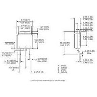
... Schottky “Q” series - Voltage rating ( TO-252AA (D-PAK) - None = Tube (50 pieces Tape and reel TRL = Tape and reel (left oriented) TRR = Tape and reel (right oriented) - PbF = Lead (Pb)-free LINKS TO RELATED DOCUMENTS DiodesEurope@vishay.com VS-30WQ06FNPbF Vishay Semiconductors TRL PbF 7 8 www.vishay.com/doc?95016 www.vishay.com/doc?95059 www.vishay.com/doc?95033 www.vishay.com 5 ...

Page 6

... Vishay product could result in personal injury or death. Customers using or selling Vishay products not expressly indicated for use in such applications their own risk and agree to fully indemnify and hold Vishay and its distributors harmless from and against any and all claims, liabilities, expenses and damages arising or resulting in connection with such use or sale, including attorneys fees, even if such claim alleges that Vishay or its distributor was negligent regarding the design or manufacture of the part ...

Related keywords