BYW55-TAP Vishay, BYW55-TAP Datasheet - Page 2
BYW55-TAP
Manufacturer Part Number
BYW55-TAP
Description
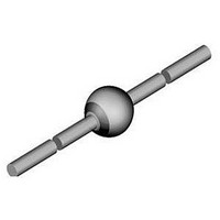
AVALANCHE DIODE, 2A, 800V, SOD-57
Manufacturer
Vishay
Datasheet
1.BYW54-TR.pdf
(4 pages)
Specifications of BYW55-TAP
Repetitive Reverse Voltage Vrrm Max
800V
Forward Current If(av)
2A
Forward Voltage Vf Max
1V
Reverse Recovery Time Trr Max
4µs
Forward Surge Current Ifsm Max
50A
Diode Type
Fast Recovery
Product
Standard Recovery Rectifier
Configuration
Single
Reverse Voltage
800 V
Forward Voltage Drop
1 V at 1 A
Recovery Time
4000 ns
Forward Continuous Current
2 A
Max Surge Current
50 A
Reverse Current Ir
1 uA
Mounting Style
SMD/SMT
Package / Case
SOD-57
Maximum Operating Temperature
+ 175 C
Minimum Operating Temperature
- 55 C
Lead Free Status / RoHS Status
Lead free / RoHS Compliant
Available stocks
Company
Part Number
Manufacturer
Quantity
Price

Part Number:
BYW55-TAP
Manufacturer:
VISHAY/威世
Quantity:
20 000


TYPICAL CHARACTERISTICS (T
Document Number: 86049
Rev. 1.7, 25-Aug-10
ELECTRICAL CHARACTERISTICS (T
PARAMETER
Forward voltage
Reverse current
Breakdown voltage
Diode capacitance
Reverse recovery time
Reverse recovery charge
16350
Fig. 1 - Typ. Thermal Resistance vs. Lead Length
0.001
Fig. 2 - Forward Current vs. Forward Voltage
0.01
120
100
949101
0.1
10
80
60
40
20
0
1
0.0
0
T
5
l
L
0.4
= constant
V
F
T
l - Lead Length (mm)
j
- Forward Voltage (V)
= 175 °C
10
DiodesAmericas@vishay.com, DiodesAsia@vishay.com,
l
For technical questions within your region, please contact one of the following:
0.8
15
T
j
= 25 °C
I
R
1.2
20
I
F
= 100 μA, t
I
F
= 1 A, dI/dt = 5 A/μs, V
= 0.5 A, I
amb
V
l
F
Standard Avalanche Sinterglass
25
R
V
TEST CONDITION
= 1 A, dI/dt = 5 A/μs
1.6
R
= V
= 25 °C, unless otherwise specified)
= 4 V, f = 1 MHz
V
RRM
p
amb
30
R
I
R
/T = 0.01, t
F
BYW52, BYW53, BYW54, BYW55, BYW56
= 1 A, i
= V
= 1 A
, T
= 25 °C, unless otherwise specified)
RRM
j
= 100 °C
R
= 0.25 A
p
R
Diode
= 0.3 ms
= 50 V
SYMBOL
V
Q
C
V
I
I
(BR)
t
t
16351
16352
Fig. 4 - Reverse Current vs. Junction Temperature
R
R
rr
rr
F
D
rr
1000
DiodesEurope@vishay.com
100
2.5
2.0
1.5
1.0
0.5
0.0
10
Fig. 3 - Max. Average Forward Current vs.
1
25
0
V
20
R
MIN.
T
= V
amb
50
T
-
-
-
-
-
-
-
-
PCB: d = 25 mm
R
j
Ambient Temperature
40
RRM
- Junction Temperature (°C)
thJA
- Ambient Temperature (°C)
Vishay Semiconductors
= 100 K/W
60
75
80 100 120 140 160 180
TYP.
0.9
0.1
100
18
5
-
-
-
-
R
125
half sine wave
thJA
l = 10 mm
V
R
= 45 K/W
= V
MAX
1600
200
150
10
RRM
1
1
4
4
-
www.vishay.com
175
UNIT
μA
μA
pF
nC
μs
μs
V
V
159
Related parts for BYW55-TAP
Image
Part Number
Description
Manufacturer
Datasheet
Request
R

Part Number:
Description:
AVALANCHE DIODE, 2A, 800V, SOD-57
Manufacturer:
Vishay
Datasheet:

Part Number:
Description:
357-036-542-201 CARDEDGE 36POS DL .156 BLK LOPRO
Manufacturer:
Vishay
Datasheet:
Part Number:
Description:
357-036-542-201 CARDEDGE 36POS DL .156 BLK LOPRO
Manufacturer:
Vishay
Datasheet:
Part Number:
Description:
357-036-542-201 CARDEDGE 36POS DL .156 BLK LOPRO
Manufacturer:
Vishay
Datasheet:
Part Number:
Description:
357-036-542-201 CARDEDGE 36POS DL .156 BLK LOPRO
Manufacturer:
Vishay
Datasheet:
Part Number:
Description:
357-036-542-201 CARDEDGE 36POS DL .156 BLK LOPRO
Manufacturer:
Vishay
Datasheet:
Part Number:
Description:
357-036-542-201 CARDEDGE 36POS DL .156 BLK LOPRO
Manufacturer:
Vishay
Datasheet:
Part Number:
Description:
357-036-542-201 CARDEDGE 36POS DL .156 BLK LOPRO
Manufacturer:
Vishay
Datasheet:
Part Number:
Description:
357-036-542-201 CARDEDGE 36POS DL .156 BLK LOPRO
Manufacturer:
Vishay
Datasheet:
Part Number:
Description:
357-036-542-201 CARDEDGE 36POS DL .156 BLK LOPRO
Manufacturer:
Vishay
Datasheet:
Part Number:
Description:
357-036-542-201 CARDEDGE 36POS DL .156 BLK LOPRO
Manufacturer:
Vishay
Datasheet:
Part Number:
Description:
357-036-542-201 CARDEDGE 36POS DL .156 BLK LOPRO
Manufacturer:
Vishay
Datasheet:
Part Number:
Description:
357-036-542-201 CARDEDGE 36POS DL .156 BLK LOPRO
Manufacturer:
Vishay
Datasheet:
Part Number:
Description:
357-036-542-201 CARDEDGE 36POS DL .156 BLK LOPRO
Manufacturer:
Vishay
Datasheet: