VS-130MT120KPBF Vishay, VS-130MT120KPBF Datasheet - Page 5
VS-130MT120KPBF
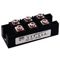
Manufacturer Part Number
VS-130MT120KPBF
Description
Bridge Rectifier
Manufacturer
Vishay
Datasheet
1.130MT80KPBF.pdf
(7 pages)
Specifications of VS-130MT120KPBF
No. Of Phases
Three
Repetitive Reverse Voltage Vrrm Max
1.2kV
Forward Current If(av)
130A
Forward Voltage Vf Max
1.63V
Leaded Process Compatible
Yes
Package / Case
INT-A-Pak
Lead Free Status / RoHS Status
Lead free / RoHS Compliant


www.irf.com
1000
900
800
700
600
500
400
300
200
150
140
130
120
110
100
90
80
70
60
50
Number Of Equal Amplitude Half Cycle Current Pulses (N)
Fig. 4 - Maximum Non-Repetitive Surge Current
1
0
Fig. 6 - Current Ratings Characteristics
130MT..K Series
500
450
400
350
300
250
200
150
100
At Any Rated Load Condition And With
Rated V
50
40
0
0
Total Output Current (A)
130MT..K Series
T = 150°C
J
RRM
20
80
Total Output Current (A)
Applied Following Surge.
40
120
10
160MT..K Series
60
@ 60 Hz 0.0083 s
@ 50 Hz 0.0100 s
(Rect)
120°
Initial T = 150°C
160
80 100 120 140 160
Fig. 3 - Total Power Loss Characteristics
J
(Rect)
120°
200
100
240
0
Maximum Allowable Ambient Temperature (°C)
25
1200
1100
1000
1000
50
900
800
700
600
500
400
300
200
100
10
Fig. 5 - Maximum Non-Repetitive Surge Current
1
0.01
Fig. 7 - Forward Voltage Drop Characteristics
0
75
130-160MT..KPbF Series
Maximum Non Repetitive Surge Current
130MT..K Series
Instantaneous Forward Voltage (V)
100
1
Pulse Train Duration (s)
Versus Pulse Train Duration.
125
T = 25°C
T = 150°C
2
J
J
Bulletin I27216 03/06
Rated V
0.1
No Voltage Reapplied
160MT..K Series
Per Junction
150
3
Initial T = 150°C
RRM
Reapplied
J
4
5
5
1
Related parts for VS-130MT120KPBF
Image
Part Number
Description
Manufacturer
Datasheet
Request
R

Part Number:
Description:
SCHOTTKY RECTIFIER, 65A, 15V, TO-247AC
Manufacturer:
Vishay
Datasheet:

Part Number:
Description:
Rectifiers 1200 Volt 2x8 Amp Common Cathode
Manufacturer:
Vishay
Part Number:
Description:
Insulated Ultrafast Rectifier Module, 130 A
Manufacturer:
Vishay
Datasheet:

Part Number:
Description:
Rectifiers 130 Amp 200 Volt
Manufacturer:
Vishay Semiconductors
Datasheet:
Part Number:
Description:
Bridge Rectifiers 800 Volt 130 Amp
Manufacturer:
Vishay Semiconductors
Datasheet:
Part Number:
Description:
Bridge Rectifiers 1000 Volt 130 Amp
Manufacturer:
Vishay Semiconductors
Datasheet:
Part Number:
Description:
Bridge Rectifiers 1400 Volt 130 Amp
Manufacturer:
Vishay Semiconductors
Datasheet:
Part Number:
Description:
Rectifiers 130 Amp 400 Volt
Manufacturer:
Vishay Semiconductors
Datasheet:
Part Number:
Description:
Rectifiers 1200 Volt 8.0 Amp
Manufacturer:
Vishay Semiconductors
Datasheet:
Part Number:
Description:
Rectifiers 1200 Volt 8.0 Amp
Manufacturer:
Vishay Semiconductors
Datasheet:
Part Number:
Description:
Rectifiers 130 Amp 600 Volt
Manufacturer:
Vishay Semiconductors
Datasheet:
Part Number:
Description:
Schottky Diodes & Rectifiers 0.5 Amp 30 Volt
Manufacturer:
Vishay Semiconductors