VBO 40-12NO6 IXYS SEMICONDUCTOR, VBO 40-12NO6 Datasheet
VBO 40-12NO6
Manufacturer Part Number
VBO 40-12NO6
Description
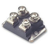
BRIDGE RECTIFIER, 1PH, 20A, 1.2KV, SCREW
Manufacturer
IXYS SEMICONDUCTOR
Datasheet
1.VBO40-08NO6.pdf
(2 pages)
Specifications of VBO 40-12NO6
No. Of Phases
Single
Repetitive Reverse Voltage Vrrm Max
1.2kV
Forward Current If(av)
20A
Forward Voltage Vf Max
1.15V
Diode Mounting Type
Panel
Lead Free Status / RoHS Status
Lead free / RoHS Compliant


Single Phase
Rectifier Bridge
Symbol
I
I
I
I
T
T
T
V
M
Weight
Symbol
I
V
V
r
R
R
d
d
a
Data according to IEC 60747 and refer to a single diode unless otherwise stated
© 2000 IXYS All rights reserved
1300
1700
dAV
dAV
FSM
2
R
T
V
t
VJ
VJM
stg
S
A
ISOL
F
T0
900
thJC
thCH
d
for resistive load at bridge output
V
RSM
1200
1600
V
800
RRM
Test Conditions
T
T
V
T
V
T
V
T
V
50/60 Hz, RMS
Mounting torque (M4)
Terminal connection torque (M4)
typ.
Test Conditions
V
V
I
For power-loss calculations only
T
per diode; DC current
per module
per diode, DC current
per module
Creeping distance on surface
Creepage distance in air
Max. allowable acceleration
V
F
C
VJ
VJ
VJ
VJ
VJ
R
R
R
R
R
R
= 100°C
= 0
= 0
= 0
= 0
= 45°C;
= T
= 45°C
= T
= T
= V
= V
= 20 A;
VJM
VJM
VJM
RRM
RRM
Standard
Types
VBO 40-08NO6
VBO 40-12NO6
VBO 40-16NO6
;
;
(diode)
(module)
t = 10 ms (50 Hz), sine
t = 8.3 ms (60 Hz), sine
t = 10 ms (50 Hz), sine
t = 8.3 ms (60 Hz), sine
t = 10 ms (50 Hz), sine
t = 8.3 ms (60 Hz), sine
t = 10 ms (50 Hz), sine
t = 8.3 ms (60 Hz), sine
T
T
T
VJ
VJ
VJ
I
= 25°C
= T
= 25°C
ISOL
VJM
£ 1 mA
Characteristic Values
typ.
typ.
Maximum Ratings
£
£
£
~
~
-40...+150
-40...+125
1.5/13 Nm/lb.in.
1.5/13 Nm/lb.in.
2500
1.15
0.80
0.42
0.08
300
320
260
280
450
430
340
330
150
0.3
0.3
1.7
20
40
30
13
50
5
8
4
K/W
K/W
K/W
K/W
m/s
mW
mm
mm
mA
mA
V~
A
A
A
A
V
V
°C
°C
°C
A
A
A
A
A
A
g
2
2
2
2
s
s
s
s
2
+
–
I
V
miniBLOC, SOT-227 B
Features
Applications
Advantages
dAV
Isolation voltage 2500 V~
Planar passivated chips
Low forward voltage drop
Supplies for DC power equipment
Input rectifiers for PWM inverter
Battery DC power supplies
Field supply for DC motors
Easy to mount
Space and weight savings
M4 screws (4x)
supplied
RRM
Dim.
A
B
C
D
E
F
G
H
J
K
L
M
N
O
P
Q
R
S
T
U
V
W
E72873
31.50
14.91
30.12
37.80
11.68
12.60
25.15
26.54
24.59
0.780
= 40 A
= 800-1600 V
-0.05
7.80
4.09
4.09
4.09
8.92
0.76
1.98
4.95
3.94
4.72
3.30
Min.
Millimeter
~
31.88
15.11
30.30
38.30
12.22
12.85
25.42
26.90
25.07
0.830
Max.
8.20
4.29
4.29
4.29
9.60
0.84
2.13
5.97
4.42
4.85
4.57
0.1
–
~
-0.002
1.240
0.307
0.161
0.161
0.161
0.587
1.186
1.489
0.460
0.351
0.030
0.496
0.990
0.078
0.195
1.045
0.155
0.186
0.968
0.130
19.81
Min.
+
VBO 40
Inches
1.255
0.323
0.169
0.169
0.169
0.595
1.193
1.509
0.481
0.378
0.033
0.506
1.001
0.084
0.235
1.059
0.174
0.191
0.987
0.004
0.180
21.08
Max.
1 - 2
Related parts for VBO 40-12NO6
Image
Part Number
Description
Manufacturer
Datasheet
Request
R

Part Number:
Description:
BRIDGE RECTIFIER, 40A, 800V
Manufacturer:
IXYS SEMICONDUCTOR
Datasheet:

Part Number:
Description:
Discrete Semiconductor Modules 1000 Amps 100V
Manufacturer:
IXYS
Datasheet:
Part Number:
Description:
Discrete Semiconductor Modules 300 Amps 1200V
Manufacturer:
IXYS
Datasheet:
Part Number:
Description:
Discrete Semiconductor Modules 450 Amps 1200V
Manufacturer:
IXYS
Datasheet:
Part Number:
Description:
Discrete Semiconductor Modules
Manufacturer:
IXYS
Datasheet:
Part Number:
Description:
Discrete Semiconductor Modules 1500 Amps 75V
Manufacturer:
IXYS
Datasheet:
Part Number:
Description:
Discrete Semiconductor Modules 300 Amps 1200V
Manufacturer:
IXYS
Datasheet:
Part Number:
Description:
Discrete Semiconductor Modules 225 Amps 1200V
Manufacturer:
IXYS
Datasheet:

Part Number:
Description:
DIODE MODULE EPITAXIAL 600V 95A
Manufacturer:
IXYS
Datasheet:

Part Number:
Description:
MODULE IGBT CBI E1
Manufacturer:
IXYS
Datasheet:

Part Number:
Description:
MODULE IGBT CBI E2
Manufacturer:
IXYS
Datasheet:

Part Number:
Description:
MOSFET N-CH 100V 1245A Y3-LI
Manufacturer:
IXYS
Datasheet:

Part Number:
Description:
THYRISTOR DIODE MODULE
Manufacturer:
IXYS
Datasheet:

Part Number:
Description:
FAST RECTIFIER, DUAL, 123A SOT-227B
Manufacturer:
IXYS SEMICONDUCTOR
Datasheet:
Part Number:
Description:
FAST RECTIFIER, DUAL, 96A, SOT-227B
Manufacturer:
IXYS SEMICONDUCTOR
Datasheet:
VBO 40-12NO6 Summary of contents
Page 1
... Single Phase Rectifier Bridge V V Standard RSM RRM V V Types 900 800 VBO 40-08NO6 1300 1200 VBO 40-12NO6 1700 1600 VBO 40-16NO6 Symbol Test Conditions 100°C (diode) dAV C I (module) dAV 45° (50 Hz), sine FSM 8.3 ms (60 Hz), sine (50 Hz), sine ...
Page 2
... Fig versus time per diode thHA d(AV ° 100 120 140 Fig. 5 Max. forward current versus case temperature Constants for Z calculation: thJC i R (K/W) thi 1 0.081 2 0.1449 3 0.2982 4 0.735 5 0.441 VBO VBO 150° ° (s) i 0.00024 0.0036 0.0235 0.142 0 ...