GBPC106-E4 Vishay, GBPC106-E4 Datasheet - Page 3
GBPC106-E4
Manufacturer Part Number
GBPC106-E4
Description
BRIDGE RECTIFIER, 1PH, 3A, 600V THD
Manufacturer
Vishay
Datasheet
1.GBPC104-E451.pdf
(4 pages)
Specifications of GBPC106-E4
No. Of Phases
Single
Repetitive Reverse Voltage Vrrm Max
600V
Forward Current If(av)
3A
Forward Voltage Vf Max
1V
Diode Mounting Type
Through Hole
Operating Temperature Range
-55°C To +150°C
Lead Free Status / RoHS Status
Lead free / RoHS Compliant


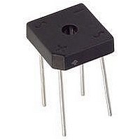
PACKAGE OUTLINE DIMENSIONS in inches (millimeters)
Document Number: 88611
Revision: 15-Apr-08
Figure 4. Typical Reverse Leakage Characteristics Per Diode
0.01
0.01
100
100
0.1
0.1
10
Figure 3. Typical Forward Characteristics Per Diode
10
1
1
0.4
0
T
Pulse Width = 300 µs
1 % Duty Cycle
Percent of Rated Peak Reverse Voltage (%)
J
= 25 °C
0.6
Instantaneous Forward Voltage (V)
20
0.8
40
PDD-Americas@vishay.com, PDD-Asia@vishay.com, PDD-Europe@vishay.com
For technical questions within your region, please contact one of the following:
1.0
60
1.2
T
T
J
J
Polarity shown on side of case: Positive lead by beveled corner
80
= 125 °C
= 25 °C
Hole For #6 Screw
1.4
0.630 (16.00)
0.590 (14.98)
0.158 (4.01)
0.142 (3.61)
0.032 (0.81)
0.028 (0.71)
0.200 (5.08)
0.160 (4.06)
0.128 (3.25)
0.048 (1.22)
100
1.6
DIA.
DIA.
Case Style GBPC1
0.445 (11.30)
0.405 (10.29)
0.630 (16.00)
0.590 (14.98)
AC
0.040 (1.02) TYP.
AC
0.094 (2.4) x 45°
Figure 6. Typical Transient Thermal Impedance Per Diode
100
100
0.1
0.445 (11.30)
0.405 (10.29)
10
10
1
Figure 5. Typical Junction Capacitance Per Diode
1
0.01
0.1
0.750 (19.05)
GBPC1005 thru GBPC110
Vishay General Semiconductor
MIN.
0.1
Reverse Voltage (V)
t - Heating Time (s)
1
1
10
T
f = 1.0 MHz
V
J
sig
10
= 25 °C
= 50 mVp-p
www.vishay.com
100
100
3
Related parts for GBPC106-E4
Image
Part Number
Description
Manufacturer
Datasheet
Request
R

Part Number:
Description:
DIODE GPP 1PH 3A 600V GBPC1
Manufacturer:
Vishay
Datasheet:


Part Number:
Description:
Glass Passivated Single-Phase Bridge Rectifier
Manufacturer:
Vishay Telefunken

Part Number:
Description:
12, 15, 25, 35 Ampere Glass Passivated Bridge Rectifiers
Manufacturer:
Fairchild Semiconductor
Part Number:
Description:
GLASS PASSIVATED BRIDGE RECTIFIERS
Manufacturer:
HY Electronic Co., Ltd.
Part Number:
Description:
GLASS PASSIVATED BRIDGE RECTIFIERS
Manufacturer:
HY Electronic Co., Ltd.
Part Number:
Description:
GLASS PASSIVATED BRIDGE RECTIFIERS
Manufacturer:
HY Electronic Co., Ltd.
Part Number:
Description:
Bridge Rectifier
Manufacturer:
RFE International, Inc.
Datasheet:

Part Number:
Description:
GBPC/GBPC/35A/200V/Gen.Purp. Bridge Rect./Leaded/GP
Manufacturer:
Pan Jit International Inc.
Part Number:
Description:
GBPC-W/15A/200V/Gen.Purp. Bridge Rect./Leaded/GP
Manufacturer:
Pan Jit International Inc.
Part Number:
Description:
GBPC-W/25A/800V/Gen.Purp. Bridge Rect./Leaded/GP
Manufacturer:
Pan Jit International Inc.
Part Number:
Description:
GBPC-W/35A/600V/Gen.Purp. Bridge Rect./Leaded/GP
Manufacturer:
Pan Jit International Inc.
Part Number:
Description:
GBPC-W/35A/1000V/Gen.Purp. Bridge Rect./Leaded/GP
Manufacturer:
Pan Jit International Inc.

Part Number:
Description:
Bridge Rectifiers 12 Amp 600 Volt
Manufacturer:
Vishay
Datasheet: