MF1-B-34-610-1-DB2-2-C Carling Technologies, MF1-B-34-610-1-DB2-2-C Datasheet
MF1-B-34-610-1-DB2-2-C
Specifications of MF1-B-34-610-1-DB2-2-C


Related parts for MF1-B-34-610-1-DB2-2-C


MF1-B-34-610-1-DB2-2-C Summary of contents
Page 1
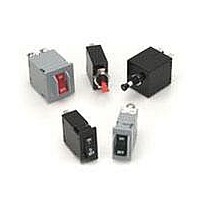
... Requires Branch Circuit Backup with a UL Listed type K-5 or RK-5 fuse rated 60 Amps maximum 18 The low cost M-Series utilizes the hydraulic magnetic principle which provides accurate and reliable circuit protection even when exposed to extremely hot and/or cold application environments. Available in a choice of rocker actuator styles and colors, push ...
Page 2
Electrical Table B: Lists UL Recognized,CSA Accepted and TUV and VDE Certified configurations and performance capabilities as a Component Supplementary Protector. NOTES FOR TABLE B 1 Polarity Sensitive 2 Available only with Special Catalog Number. Consult Factory. 3 Requires Branch ...
Page 3
M-Series General Specifications Electrical Maximum Voltage 125/250 VAC 50/60 Hz, 80 VDC (See Rating Tables.) Current Ratings Standard current coils: 0.100, 0.250, 0.500, 0.750, 1.00 thru 15 amp increments, 18.0, 20.0, 25.0, 30.0. Other ratings avail- able - ...
Page 4
Series Actuator Poles Circuit 1 SERIES M 2 ACTUATOR 1 Handle M Paddle N Baton Push Button T Push-Pull U Push To Reset Push Button w/ Snap-In Mounting V Push-Pull ...
Page 5
M-Series Handle/Pushbutton UL489A/UL Recognized – Ordering Scheme – – Series Actuator Poles Circuit 1 SERIES M 2 ACTUATOR 1 Handle M Paddle N Baton Push Button T Push-Pull U Push To Reset ...
Page 6
– Series Actuator Poles Circuit 1 SERIES M 2 ACTUATOR 1 Non-Illuminated Two Color single color Visi-Rocker D Indicate ON A Angled E Indicate OFF B Flat 3 POLES 1 One ...
Page 7
M-Series Rocker UL489A/UL Recognized – Ordering Scheme – – Series Actuator Poles Circuit 1 SERIES M 2 ACTUATOR 1 Non-Illuminated single color A Angled B Two Color Visi-Rocker D Indicate ON E ...
Page 8
Notes: 1 All dimensions are in inches [millimeters]. 2 Tolerance ±.020 [.51] unless otherwise specified. www.carlingtech.com M-Series Handle – Circuit & Terminal Diagrams 25 ...
Page 9
M-Series Handle – Form & Fit Drawings Notes: 1 All dimensions are in inches [millimeters]. 2 Tolerance ± 0.20 [.51] unless otherwise specified. 26 www.carlingtech.com ...
Page 10
Notes: 1 All dimensions are in inches [millimeters]. 2 Tolerance ±.020 [.51] unless otherwise specified. www.carlingtech.com M-Series Handle – PC Terminal Diagrams 27 ...
Page 11
M-Series Pushbutton – Circuit & Terminal Diagrams Notes: 1 All dimensions are in inches [millimeters]. 2 Tolerance ±.020 [.51] unless otherwise specified. 28 www.carlingtech.com ...
Page 12
Notes: 1 All dimensions are in inches [millimeters]. 2 Tolerance ± 0.20 [.51] unless otherwise specified. 3 Available with Push-Pull or Push-to-Reset Actuators. www.carlingtech.com M-Series Pushbutton – Form & Fit Drawings 29 ...
Page 13
M-Series Push-Pull – PC Terminal Drawings Notes: 1 All dimensions are in inches [millimeters]. 2 Tolerance ±.020 [.51] unless otherwise specified. 30 www.carlingtech.com ...
Page 14
Notes: 1 All dimensions are in inches [millimeters]. 2 Tolerance ±.020 [.51] unless otherwise specified. 3 Schematic shown represents current trip circuit. www.carlingtech.com M-Series Rocker – Circuit & Terminal Diagrams 31 ...
Page 15
M-Series Rocker – Form & Fit Drawings Notes: 1 Dimensions apply to all variations shown. Notice that circuit breaker line & load terminal orientation on indicate OFF is opposite of indicate ON. 2 I-O, ON-OFF or dual legends available for ...
Page 16
M-Series Rocker – Supplementary Diagrams 33 ...