P-312-CCT Cinch Connectors, P-312-CCT Datasheet - Page 66
P-312-CCT
Manufacturer Part Number
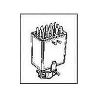
P-312-CCT
Description
CONN PLUG 12POS JONES SOLDER MNT
Manufacturer
Cinch Connectors
Series
300r
Type
Cable Plugr
Specifications of P-312-CCT
Connector Type
Plug, Jones
Contact Type
Tab
Number Of Positions
12
Pitch
0.156" (3.96mm)
Number Of Rows
3
Row Spacing
0.156" (3.96mm)
Mounting Type
Free Hanging (In-Line)
Cable Termination
Solder Eyelet
Wire Type
Discrete
Features
Cable Clamp
Contact Finish
Cadmium
Color
Black
Contact Termination
Solder
No. Of Contacts
12
No. Of Rows
2
Connector Mounting
Cable
Gender
Plug
Contact Material
Brass
Contact Plating
Cadmium
Agency Approvals
CSA, UL
Angle
Straight
Brand/series
300 Series
Current, Rating
10 A
Diameter
0.563 in.
Flammability Rating
UL94V-0
Length, Overall
1.286 "
Material, Contact
Brass
Material, Dielectric
Phenolic
Material, Hood
Thermoplastic
Material, Insulation
Phenolic
Number Of Contacts
12
Plating, Contact
Cadmium
Primary Type
Jones
Special Features
Polarized
Standards
UL Recognized File No: E170218 (UL 1977), E130965 (UL1863), CSA-LR31996
Temperature, Operating
0 to +105 °C
Termination
Solder
Thickness
0.974 in. ± 0.016 in.
Voltage, Rating
250 V
Width
1.286 in. ± 0.016 in.
Contact Gender
Pin
Rohs Compliant
No
Current Rating
10 A
Housing Material
Thermoplastic
Number Of Positions / Contacts
12
Voltage Rating
250 V
Lead Free Status / RoHS Status
Contains lead / RoHS non-compliant
Contact Finish Thickness
-
Fastening Type
-
For Use With
Cable to panel & cable to cable applications
Lead Free Status / Rohs Status
No
Other names
CJ112P
P-312-CCT-P
P312CCT-P
P-312-CCT-P
P312CCT-P


CARDCON
Edge Connector
Commercial
Insulation Material: UL 94V-0 rated glass-filled polyester, black
Contact Material: Spring brass
Contact Plating: 10µ" selective gold over 30µ" nickel in contact
Shock: Per MIL-STD-202E, Method 213, Condition C
Operating Temperature: -65°C to +105°C
Vibration: Per MIL-STD-202E, Method 204, Condition B
Humidity: Per MIL-STD-202, Method 103, Condition B
Accessories:
Polarizing Key: Two types (order separately):
a) for between-contact polarization and
b) for in-contact polarization
See page 2-72 for more information.
Card Guide Posts: (order separately):
Attach to mounting ears and guide PC board into connector
See page 2-72 for more information.
Individual Contact Insertion and Separation Force:
Call Toll Free: 1 (800) 323-9612
Dip solder tails single readout and double readout on .140" (3.56mm) row
centers or .200" (5.08mm) row centers.
Solder eyelet, single readout and double readout on .200" (5.08mm)
row centers.
Available with unique tails for PC board retention; holds the connector
firmly on the board during wave soldering operations.
Bifurcated semi-bellows contacts for added contact reliability.
Ideal for applications involving vibration or board irregularities.
Contact positions: 6, 10, 12, 15, 18, 22, 24, and 25.
Accepts single- or double-sided .062" (1.59mm) thick PC boards.
Available less mounting ears or with .128" (3.25mm) mounting hole.
Meets applicable performance criteria of MIL-C-21097.
UL Recognized - file E170218 (UL1977) E130965 (UL1863).
16 oz. maximum with .070" (1.78mm) blade;
1 oz. minimum with .054" (1.37mm) blade
Insulation Resistance:
Withstanding Voltage:
Contact Resistance:
™
Current Rating:
area, tin on tails
1800 VAC RMS (@ sea level)
5 Amps
6 Milliohms maximum
5000 Megohms minimum
.156" (3.96mm) Density
Dip Solder/Solder Eyelet
2-64
Marketed exclusively through distribution.
Related parts for P-312-CCT
Image
Part Number
Description
Manufacturer
Datasheet
Request
R

Part Number:
Description:
IC & Component Sockets DISC-MFG-1/01 12C CBL MNT PLUG
Manufacturer:
Cinch Connectors
Part Number:
Description:
IC & Component Sockets 12C PNL MNT PLUG
Manufacturer:
Cinch Connectors
Part Number:
Description:
IC & Component Sockets 12C PNL MNT PLUG
Manufacturer:
Cinch Connectors

Part Number:
Description:
CONN PLUG 3POS JONES SOLDER MNT
Manufacturer:
Cinch Connectors
Datasheet:
Part Number:
Description:
CONN PLUG 3POS W/BRACKET PNL MNT
Manufacturer:
Cinch Connectors
Datasheet: