NZMN1-A125 MOELLER, NZMN1-A125 Datasheet
NZMN1-A125
Specifications of NZMN1-A125


Related parts for NZMN1-A125


NZMN1-A125 Summary of contents
Page 1
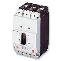
... Type: NZMN1−A125 Article No.: 259086 Sales text Circuit−breaker3p systems/cable prot. Ordering information Number of poles Description Rated current = rated uninterrupted current Setting range Overload releases Switching capacity Switching capacity Release system Frame size Notes concerning the product group IEC/EN 60947−2 Adjustable overload release I 0.8 ... 1 × ...
Page 2
− NZM...−A40: 8 ... 10 × I (ex−works 8 × Fixed short−circuit release I i 350 ... 1280 160 A ...
Page 3
Enclosures Terminations Lifespan Releases Electrical lifespan at 8 A/230 V AC/70 °C Circuit−breakers Rated impulse withstand voltage U Main contacts Auxiliary contacts Rated operational voltage Overvoltage category/pollution degree Rated insulation voltage For use in IT electrical power networks Switching capacity ...
Page 4
V 50/60 Hz 415 440 V 50/60 Hz 525 V 50/ 690 V 50/60 Hz 690 V AC Maximum low−voltage h.b.c. fuse Technical data, divergent from the products for the IEC marketSwitching ...
Page 5
Frequency range Terminal capacities Standard equipment Accessories Rated power of coil Box terminal Solid Stranded Tunnel terminal Solid Stranded Single hole Bolt terminal and rear−side connection Direct on the switch Solid Stranded Al conductors, Cu cable Tunnel terminal Solid Stranded ...
Page 6
Bolt terminal and rear−side connection Screw connection Direct on the switch Notes Notes Mounting position Vertical and 90° in all directions With residual−current release NZM1, N(S)1: Vertical and 90° in all directions min × 5 ...
Page 7
Overview Basic equipment Box terminal Screw connection – Accessories Box terminal – Screw connection Tunnel terminal Connection on rear Flat conductor terminal – – – Notes For rated operational voltage switching on 3 contacts the following applies: DC correction factor ...
Page 8
A Higher switching capacity on request Notes XSV = plug−in unit XAV = withdrawable unit TM = thermomagnetic E = electronic Dimensions Blow out area, minimum clearance to other parts 60 mm Dimensions 8 ...
Page 9
Characteristic curve 9 ...
Page 10
System and line protection with NZM1 Characteristic curve 10 ...
Page 11
Let−through current î Let−through energy I t Characteristic curve 11 ...
Page 12
... Moeller GmbH, Hein−Moeller−Str. 7−11, D−53115 Bonn E−Mail: catalog@moeller.net, Internet: www.moeller.net, http://catalog.moeller.net Copyright 2006 by Moeller GmbH. HPL−C2007G V2.1 12 ...