3RV10110JA10 SIEMENS, 3RV10110JA10 Datasheet - Page 51
3RV10110JA10
Manufacturer Part Number
3RV10110JA10
Description
CIRCUIT-BR, 0.70/1A
Manufacturer
SIEMENS
Series
3RVr
Datasheet
1.3RV19011A.pdf
(56 pages)
Specifications of 3RV10110JA10
No. Of Poles
3
Voltage Rating Vac
690V
Mounting Type
DIN Rail (EN 50022)
Approval Bodies
UL, CSA, VDE
Breaking Capacity Current Ac
100kA
Current Max
1.00A
Current Min
0.70A
External Depth
81mm


■
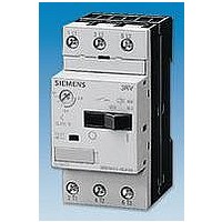
Overview
(1) Connection for mounting onto contactors:
(2) Selector switch for manual/automatic RESET and RESET button:
(3) Switch position indicator and TEST function of the wiring:
(4) Motor current setting:
(5) STOP button:
(6) Transparent, sealable cover:
(7) Supply terminals:
The 3RU11 thermal overload relays up to 100 A have been
designed for current-dependent protection of loads with normal
starting
rises due to overload or phase failure. An overload or phase
failure results in an increase of the motor current beyond the set
motor rated current. Via heating elements, this current rise heats
up the bimetal strips inside the device, which then bend and as
a result trigger the auxiliary contacts by means of a tripping
mechanism. The auxiliary contacts then switch off the load by
means of a contactor. The break time depends on the ratio
between the tripping current and set current I
the form of a long-term stable tripping characteristic
Characteristic
The "tripped" status is signaled by means of a switch position
indicator
manually or automatically after the recovery time has elapsed
(see LV 1 T,
The devices are manufactured in accordance with
environmental guidelines and contain environmentally friendly
and reusable materials.
They comply with all important worldwide standards and
approvals.
Optimally adapted in electrical, mechanical and design terms to the
contactors, these connecting pins can be used for direct mounting of
the overload relays. Stand-alone installation is possible as an
alternative (in some cases in conjunction with a stand-alone
installation module).
With this switch you can choose between manual and automatic
RESET. A device set to manual RESET can be reset locally by pressing
the RESET button. A remote RESET is possible using the RESET
modules (accessories), which are independent of size.
Indicates a trip and enables the wiring test.
Setting the device to the rated motor current is easy with the large
rotary knob.
If the STOP button is pressed, the NC contact is opened. This switches
off the contactor downstream. The contactor is switched on again
when the STOP button is released.
Secures the motor current setting, TEST function and the selector
switch for manual/automatic RESET against adjustment.
The generously sized terminals permit connection of two conductors
with different cross-sections for the main and auxiliary circuits. The
auxiliary circuit can be connected with screw-type terminals and
alternatively with spring-loaded terminals.
(see LV 1 T, Function)
(see LV 1 T,
Function).
Curves).
Function). Resetting takes place either
against excessive temperature
e
and is stored in
(see LV 1 T,
■
■
Benefits
The most important features and benefits of the 3RU11 thermal
overload relays are listed in the overview table
Relays, General
Application
Industries
The 3RU11 thermal overload relays are suitable for customers
from all industries who want to guarantee optimum inverse-time
delayed protection of their electrical loads (e.g. motors) under
normal starting conditions (CLASS 10).
Application
The 3RU11 thermal overload relays have been designed for the
protection of three-phase and single-phase AC and DC motors.
If single-phase AC or DC loads are to be protected by the 3RU11
thermal overload relays, all three bimetal strips must be heated.
For this purpose, all main circuits of the relay must be connected
in series.
Ambient conditions
The 3RU11 thermal overload relays have temperature
compensation in accordance with IEC 60947-4-1 for the
temperature range of –20 to +60 °C. For temperatures from
+60 to +80 °C the upper setpoint value of the setting range must
be reduced by the factor listed in the table below.
"Increased safety" type of protection EEx e according to
ATEX guideline 94/9/EC
The 3RU11 thermal overload relays are suitable for the overload
protection of explosion-proof motors with "increased safety" type
of protection EEx e. The relays meet the requirements of
EN 60079-7 (Electrical apparatus for potentially explosive
atmospheres – Increased safety "e").
The basic safety and health requirements of ATEX guideline
94/9/EG are fulfilled by compliance with
• EN 60947-4-1
• EN 60947-5-1
• EN 60079-14: 1997-02
• EN 60079-17: 1996-12
EU type test certificate for Category (2) G/D exists. It has the
number DMT 98 ATEX 6001.
Ambient temperature in °C
+60
+65
+70
+75
+80
3RU1 Thermal Overload Relays
Data).
3RU11 for standard applications
Overload Relays
Derating factor for
the upper setpoint value
1.0
0.94
0.87
0.81
0.73
Siemens LV 1 · 2006
(see Overload
5/51
Related parts for 3RV10110JA10
Image
Part Number
Description
Manufacturer
Datasheet
Request
R

Part Number:
Description:
Intel 80C32 - Siemens SAB-C501, Nearest Equivalent Replacement
Manufacturer:
Siemens Semiconductor Group
Part Number:
Description:
IGBT MODULE
Manufacturer:
Siemens Semiconductor Group
Datasheet:
Part Number:
Description:
SIMOPAC Module (Power module Single switch N channel Enhancement mode)
Manufacturer:
Siemens Semiconductor Group
Datasheet:
Part Number:
Description:
(BSMxxx) TRANSISTOR
Manufacturer:
Siemens Semiconductor Group
Datasheet:
Part Number:
Description:
SIMOPAC Module (Power module Single switch N channel Enhancement mode)
Manufacturer:
Siemens Semiconductor Group
Datasheet:
Part Number:
Description:
main ratings
Manufacturer:
Siemens Semiconductor Group
Datasheet:
Part Number:
Description:
Manufacturer:
Siemens Semiconductor Group
Datasheet:
Part Number:
Description:
Manufacturer:
Siemens Semiconductor Group
Datasheet:
Part Number:
Description:
Manufacturer:
Siemens Semiconductor Group
Datasheet:
Part Number:
Description:
ICs for Consumer Electronics
Manufacturer:
Siemens Semiconductor Group
Datasheet:
Part Number:
Description:
Video and Sound IF with V & S SCART
Manufacturer:
Siemens Semiconductor Group
Datasheet:
Part Number:
Description:
Manufacturer:
Siemens Semiconductor Group
Datasheet:
Part Number:
Description:
Multistandard Sound IF
Manufacturer:
Siemens Semiconductor Group
Datasheet:
Part Number:
Description:
MULTISTANDARD AM FM SOUND IF IC
Manufacturer:
Siemens Semiconductor Group
Datasheet: