FAZ-C2/2-NA MOELLER, FAZ-C2/2-NA Datasheet - Page 14
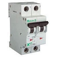
FAZ-C2/2-NA
Manufacturer Part Number
FAZ-C2/2-NA
Description
CIRCUIT BREAKER, THERMAL MAG, 2P, 2A
Manufacturer
MOELLER
Series
FAZr
Datasheet
1.FAZ-C22-NA.pdf
(18 pages)
Specifications of FAZ-C2/2-NA
Actuator Style
Toggle
No. Of Poles
2
Current Rating
2A
Voltage Rating Vdc
48V
Voltage Rating Vac
480V
Mounting Type
DIN Rail
Tripping Characteristic
C
Lead Free Status / RoHS Status
Lead free / RoHS Compliant


T T r r i i p p p p i i n n g g S S i i g g n n a a l l S S w w i i t t c c h h Z Z -N N H H K K , , Z Z -I I H H K K -N N A A
• Design according to IEC/EN 60947-5-1, IEC/EN 62019
• Can be mounted subsequently (screws)
• The specified minimum voltages are per contact
• Contact function with relative movement (self-cleaning contacts)
• Contact material and design particularly suitable for extra low voltage
• Z Z P P -N N H H K K : The function of one of the two change-over contacts can be
• Z Z -I I H H K K -N N A A : will allow for FAZ-NA > 480Y/277 VAC rating
• Tripping signal contact transmits message of electric tripping, not mechani-
• Test key for contact function “electrical tripping”
Technical Data
E E l l e e c c t t r r i i c c a a l l
Can be mounted from the left onto
Contact function
Rated voltage
Frequency
Rated current
Rated thermal current I
Utilisation category AC13
Utilisation category AC15
Utilisation category DC12
Rated insulation voltage U
Minimum operational voltage per contact U
Minimum operational current I
Rated peak withstand voltage U
Conditional short circuit current I
Max. back-up fuse, overload and short circuit
M M e e c c h h a a n n i i c c a a l l
Tripping indicator “electrical tripping”
Frame size
Device height
Device width
Mounting
Degree of protection, built-in
Terminal protection
Terminals
Terminal capacity
Terminal screws
Fastening torque of terminal screws
The voltage of the FAZ-... Circuit Breaker is limited to
300 V with this Auxiliary Switch installed.
Take into account particularly in case of series connection!
cal switch-off
Rated operational current I
Rated operational current I
Rated operational current I
with back-up fuse 6A
switched from “auxiliary switch” to “tripping signal switch”
For Moeller Electric Sales and Support call KMparts.com (866) 595-9616
th
I
imp
e
e
e
min
(1.2/50µ)
k
min
FAZ-NA, FAZ-RT, FAZ-XAA-NA
2CO
230 V
50/60 Hz
2 A
2 A
3A/250V AC
2A/250V AC
0.5A/110V DC
250 V AC
5 V DC
10 mA DC
2.5 kV
1 kA
6 A gL
blue/white
45 mm
80 mm
8.8 mm (0.5MU)
onto switching dev.
IP40
finger and hand touch safe
according to BGV A3,
ÖVE-EN 6
lift terminals
20-14 AWG
M3 (Pozidrive Z0)
7 lb-in
Z Z -N N H H K K
Connection diagram
Z-NHK
Z-IHK-NA
Z Z -I I H H K K -N N A A
1NO + 1NC
250 V
50/60 Hz
6 A
6 A
3A/250V AC
2A/250V AC
0.5A/110V DC
0.25A/220V DC
250 V AC
5 V DC
10 mA AC/DC
4 kV
1 kA
-
45 mm
80 mm
8.8 mm (0.5MU)
IP40
finger and hand touch safe
ÖVE-EN 6
lift terminals
0.5-2.5 mm²
M3 (Pozidrive Z0)
max. 1.2 Nm
according to BGV A3,
14
Related parts for FAZ-C2/2-NA
Image
Part Number
Description
Manufacturer
Datasheet
Request
R


Part Number:
Description:
SUPPLEMENTARY PROTECTOR 1P 2A C CURVE
Manufacturer:
MOELLER
Datasheet:
Part Number:
Description:
IEC ONLY SUPPLEMENTARY PROTECTOR 1P 2A C CURVE
Manufacturer:
MOELLER
Part Number:
Description:
MINIATURE BREAKER 1P 2A C CURVE RING TERMINAL
Manufacturer:
MOELLER
Part Number:
Description:
IEC ONLY SUPPLEMENTARY PROTECTOR 2P 2A C CURVE
Manufacturer:
MOELLER
Part Number:
Description:
MINIATURE BREAKER 2P 2A C CURVE RING TERMINAL
Manufacturer:
MOELLER
Part Number:
Description:
MINIATURE BREAKER 3P 2A C CURVE SCREW TERMINAL
Manufacturer:
MOELLER


Part Number:
Description:
FRONT FIXING, LED, 85-264VAC, BLUE
Manufacturer:
MOELLER
Datasheet:

Part Number:
Description:
REAR FIXING, LED, 18-30VAC/DC, GRN
Manufacturer:
MOELLER
Datasheet:
Part Number:
Description:
REAR FIXING, LED, 18-30VAC/DC, RED
Manufacturer:
MOELLER
Datasheet:
Part Number:
Description:
REAR FIXING, LED, 18-30VAC/DC, WHT
Manufacturer:
MOELLER
Datasheet: