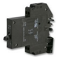
One, two and three pole thermal-magnetic circuit breakers with trip-free
mechanism and toggle actuation (S-type TM CBE to EN 60934/IEC 934).
Featuring a combi-foot design for both symmetric and asymmetric rail
mounting. Available with auxiliary contact (1 x N/O or 1 x N/C) for status
signalling. Two and three pole models are internally linked to ensure that
both/all poles trip in the event of an overload on one pole, even if the
actuator is held in the ON position. This CBE can be supplied in current
ratings up to 32 A with a choice of characteristic curves. All screw terminals
are recessed for safety. Approved to CBE standard EN 60934 (IEC 60934).
Process control equipment, robotics, machine tool control,
communications systems, instrumentation.
Type No.
2210
2210 - T 2 1 0 - K0 M1- H 1 2 1 - 10 A
Authority
VDE (EN 60934)
UL, CSA
06/07
Description
Typical applications
Ordering information
Approvals
(070706)
single and multipole thermal-magnetic circuit breaker
Mounting
T
rail mounting
Actuator design
2
toggle
Number of poles
1
2
3
5
Accessories
0
2-pole, protected on one pole only
single pole protected
2-pole protected
3-pole protected
without accessories
Terminal design (main contacts)
K0
Voltage ratings
3 AC 433 V; AC 250 V; DC 65 V
3 AC 480 V; AC 277 V;
AC 277/480 V; DC 65 V
screw terminals
Characteristic curve
F1
F2
M1
T1
T2
M3
Thermal-Magnetic Circuit Breaker 2210-T2..
fast acting: therm.1.01-1.4xI
fast acting: therm.1.01-1.4xI
magn.3,5-6,5xI
standard delay: therm. 1.01-1.4xI
magn. 6-12xI
delayed: therm. 1.01-1.4 I
thermal only, 1.01-1.4xI
standard delay, low resistance: therm. 1.4-1.8xI
magn. 6-12xI
Auxiliary contact design
H
without intermediate position
Auxiliary contacts
0
1
2
3
without auxiliary contacts
with auxiliary contacts
auxiliary contacts on pole 1 only
(multipole devices)
auxiliary contacts on pole 1 and 3
(3-pole devices)
Auxiliary contact function (see diagrams)
2
3
1 N/O contact
1 N/C contact
Auxiliary contact - terminal design
1
screw terminals
Current ratings
0.1...32 A
N
N
N
AC, 7.8-15.6xI
AC, 7.8-15.6xI
AC/4,5-8,5xI
ordering example
N
N
;
N
magn.2-4xI
; magn. 10-20xI
N
;
N
N
N
Current ratings
0.1...32 A
0.1...32 A
DC
DC
DC
N
;
N
DC (DC only)
N
www.e-t-a.com
AC
N
;
For further details please see chapter: Technical Information
Voltage rating
Current rating range
Auxiliary circuit
Typical life
Ambient temperature
Insulation co-ordination
(IEC 60664 and 60664 A)
Dielectric strength
(IEC 60664 and 60664A)
Insulation resistance
Interrupting capacity I
Interrupting capacity
(UL 1077)
Degree of protection
(IEC 60529/DIN 40050)
Vibration
Shock
Corrosion
Humidity
Mass
Technical data
3 AC 433 V; AC 250 V:
DC 65 V:
3 AC 433 V; AC 250 V:
operating area
main/aux. circuit
pole/pole
1-pole
I
1- + 2-pole AC 277 V /5,000 A
3-pole
1- + 2-pole DC 65 V /2,000 A
N
cn
AC 250 V; 3 AC 433 V (50/60 Hz); DC 65 V
(UL: AC 277/480 V; DC 65 V)
0.1...32 A for curves M1, T1, T2
0.1...16 A for curves F1, F2, M3
1 A, AC 240 V / DC 65 V
0.1...25 A
10,000 operations at 1 x I
0.1...32 A
10,000 operations at 1 x I
32 A
10,000 operations at 1 x I
-30...+60 °C (-22...+140 °F) T 60
rated impulse
2.5 kV
reinforced insulation in operating area
AC 3,000 V
AC 3,000 V
AC 1,500 V
> 100 MΩ (DC 500 V)
0.1...5 A 400 A;
curve T2 : 0.1...32 A 15 x I
curve M3: 0.1...2 A
0.1...16 A
3 AC 480 V /5,000 A 3 AC 480 V /2,000 A
operating area IP30
curve F1:
3 g (57-500 Hz), ±0.23 mm (10-57 Hz)
curves M1, M3, T1, T2:
5 g (57-500 Hz), ±0.38 mm (10-57 Hz)
to IEC 60068-2-6, test Fc
10 frequency cycles/axis
curve F1:
25 g (11 ms), directions 1, 2, 3, 4, 5
10 g (11 ms), direction 6
curves M1, M3, T1, T2:
25 g (11 ms), directions 1, 2, 3, 4, 5
20 g (11 ms), direction 6
to IEC 60068-2-27, test Ea
96 hours at 5 % salt mist
to IEC 60068-2-11, test Ka
240 hours at 95 % RH
to IEC 60068-2-3, test Ca
approx. 60 g per pole
withstand voltage
test voltage
terminal area IP20
2210-T2..
3-pole
20...32 A
AC 277 V /2,000 A
DC 65 V / 2,000 A
AC 200A /DC 400A
6...32 A 800 A;
pollution
degree
2
N
N
N
, inductive
, inductive
, resistive
N
2 - 23
2