Current
rating (A)
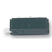
Single pole press-to-reset thermal circuit breaker with extremely fast
overload switching performance (R-type TO CBE to EN 60934). Single
hole threadneck, PCB or integral mounting with a choice of designs.
Miniaturised construction minimises PCB real estate required. Type
1410-L2 and 1410-G1 versions feature changeover contacts suitable
for providing status output signals. Largely temperature-insensitive.
Motors, transformers, solenoids, PCBs, hand-held machines, ap-
pliances, instrumentation.
Please enquire for packaging quantities.
0.63
0.8
1
1.25
1.5
1.8
2
2.5
Issue E
Type No.
1410
1410-
Standard current ratings and typical internal resistance values
Description
Typical applications
Ordering information
single pole circuit breaker
Configuration
L PCB mounting
G threadneck panel mounting
L 1 1
Mounting
1 threadneck 3/8-27 UNS-2A (1410-G)
1 PCB 16.3x4.6 grid (1410-L)
2
PCB 10.15x7.62 grid (1410-L)
Number of poles
1 1 pole, thermally protected
Internal
resistance ( )
< 1
< 1
< 1
< 1
< 0.15
1.8
1.7
1.3
Hardware
0
1
0 - L1 F1 - S 01 - 0.8 A
Thermal Overcurrent Circuit Breaker 1410-L/-G...
without
with hex nut and knurled nut (1410-G only) bulk shipped
Terminal design
L1 solder pins 1.8x0.8 silver-plated (-L1 only)
L2 solder pins 1x0.8 silver-plated (-L2 and -G1 only)
P2 blade terminals A2.8-0.8 silver-plated (-G1 only)
Characteristic curve
F1
Germany (0 91 87) 10-0 - USA (847) 827-7600 - UK (01296) 420336 - www.e-t-a.com
fast acting
Actuator
S manual re-set
Actuator colour
01 black (for -G1.. and -L1..)
02 white (for -L2..)
Current
rating (A)
10
3.15
4
4.5
5
6.3
8
Current ratings
0.63 ... 10 A
ordering example
Internal
resistance ( )
< 0.12
< 0.1
< 0.1
< 0.1
< 0.1
< 0.1
< 0.1
Voltage rating
Current rating range 1-2
Auxiliary circuit 1-3
Typical life
Ambient temperature
Insulation co-ordination
(IEC 664 and 664 A)
Dielectric strength
(IEC 664 and 664A)
Insulation resistance
Interrupting capacity I
(o-o-o)
Interrupting capacity
(UL 1077)
Degree of protection
(IEC 529/DIN 40050)
Vibration
Shock
Corrosion
Humidity
Mass
Authority
VDE
UL, CSA
Technical data
Approvals
operating area
1410-L1...
Voltage rating
AC 250 V; DC 28 V
AC 250 V; DC 50 V
cn
AC 240 V; DC 28 V (DC 50 V UL/CSA)
0.63...10 A
0.2 x I
style -L2 and -G1 only
300 operations at 2 x I
500 operations at 2 x I
-20...+100 C
Rated impulse
withstand voltage degree
2.5 kV
reinforced insulation in operating area
Test voltage
AC 1,500 V
> 100 M
0.63...2 A
2.5 ...8 A
10 A
3.15...10 A 10 x I
0.63...10 A
0.63... 8 A
operating area IP 40
8 g (57-500 Hz) 0.61 mm (10-57 Hz),
to IEC 68-2-6, Test Fc,
10 frequency cycles/axis
20 g (11 ms)
to IEC 68-2-27, test Ea
48 hours at 5 % salt mist,
to IEC 68-2-11, test Ka
96 hours at 95 % RH
to IEC 68-2-3, test Ca
approx. 5 g
terminal area IP 00
1410-L2...
N
max. 1 A, AC 250 V
(DC 500 V)
12 x I
8 x I
6 x I
2,000 A AC 250 V
N
N
N
N
, DC
, AC max. 50 A
, AC
Pollution
2
Current ratings
0.63... 8 A
0.63...10 A
200 A DC 50 V
N
N
1410-G1...
(-L2...)
(-L1../-G1..)
55
1