UEI-15/4-Q48N-C Murata Power Solutions Inc, UEI-15/4-Q48N-C Datasheet - Page 2
UEI-15/4-Q48N-C
Manufacturer Part Number
UEI-15/4-Q48N-C
Description
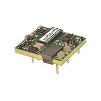
DC/DC TH Q48-15V UEI
Manufacturer
Murata Power Solutions Inc
Type
Step Downr
Datasheet
1.UEI-154-Q48N-C.pdf
(13 pages)
Specifications of UEI-15/4-Q48N-C
Output Power
60W
Number Of Outputs
1
Output Current
4A
Input Voltage
48V
Output Voltage
15V
Screening Level
Industrial
Product Height (mm)
9.7mm
Product Depth (mm)
38.1mm
Mounting Style
Through Hole
Pin Count
8
Package / Case
Case C74
Lead Free Status / Rohs Status
Details


c These are partial model numbers. Please refer to the full model number structure for complete
d Sense input is not included for 12 V
e All specifi cations are typical at nominal line voltage and full load, +25 deg.C. unless otherwise
Soldering Guidelines
Murata Power Solutions recommends the specifi cations below when installing these converters. These specifi cations vary depending on the solder type. Exceeding these specifi ca-
tions may cause damage to the product. Your production environment may differ; therefore please thoroughly review these guidelines with your process engineers.
UEI-3.3/15-Q12PR-C
UEI-3.3/18-Q48NR-C
UEI-5/10-Q12PR-C
UEI-5/12-Q48NR-C
UEI-12/4.2-Q12P-C
UEI-12/5-Q48N-C
UEI-15/3.3-Q12P-C
UEI-15/4-Q48N-C
For Sn/Ag/Cu based solders:
Maximum Preheat Temperature
Maximum Pot Temperature
Maximum Solder Dwell Time
PERFORMANCE SPECIFICATIONS AND ORDERING GUIDE
ordering part numbers.
noted. See detailed specifi cations.
PART NUMBER STRUCTURE
Root Model
Wave Solder Operations for through-hole mounted products (THMT)
c
Nominal Output Voltage
V
3.3
3.3
(V)
12
12
15
15
OUT
5
5
Maximum Rated Output
OUT
Current in Amps
115° C.
270° C.
7 seconds
15.0
18.0
10.0
12.0
I
(A)
4.2
5.0
3.3
4.0
OUT
and higher models. Sense is optional for 5 V
Input Voltage Range:
Q12 = 9-36V
Q48 = 18-75V
UEI
Power
49.5
59.4
50.0
60.0
50.4
60.0
49.5
60.0
(W)
For Sn/Pb based solders:
Maximum Preheat Temperature
Maximum Pot Temperature
Maximum Solder Dwell Time
-
3.3 15
R/N (mVp-p) Regulation (Max.)
Typ.
Output
15
60
35
70
50
40
30
35
On/Off Control Polarity:
Positive “P” polarity is standard for Q12 models and optional special
order for Q48 models. Negative “N” polarity is standard for Q48
models and optional special order for Q12 models.
/
P = Positive
N = Negative
Max.
125
100
120
100
30
50
70
60
-
Q12
±0.075% ±0.2%
±0.075% ±0.05%
±0.075% ±0.05%
±0.05% ±0.06%
±0.05% ±0.05%
±0.1%
±0.1% ±0.15%
±0.2%
Line
OUT
P R
and lower.
105° C.
250° C.
6 seconds
±0.1%
±0.2%
Load
-
Sense Inputs (5 V
C
R = Sense included as standard (for 5 V
and lower models only. 12 V
models do not offer the sense option.)
Blank = Sense not installed for 5 V
lower models. Pins 5 and 8 omitted.
Nom.
f Output capacitors are 1 μF ceramic || 10 μF electrolytic. Input cap is 22 μF, low ESR.
g I/O caps are necessary for our test equipment and may not be needed for your application.
V
(V)
RoHS-6 Hazardous Substance Compliance
(does not claim EU RoHS exemption 7b–lead in solder)
24
48
24
48
24
48
24
48
IN
Range
18-75
18-75
18-75
18-75
9-36
9-36
9-36
9-36
(V)
OUT
50-60W Isolated Wide-Range DC/DC Converters
and lower):
Input
no load
(mA)
130
130
130
130
130
130
130
I
50
IN
OUT
,
and higher
OUT
load (A)
I
IN
2.33
1.38
2.31
1.37
2.35
1.42
2.29
1.40
and
, full
OUT
86.8%
89.5%
87.8%
88.3%
87.5%
MDC_UEI Series 50-60W.C01 Page 2 of 13
Min.
87%
89%
87%
Effi ciency
Note:
Not all model number combinations are
available. Contact Murata Power Solutions.
www.murata-ps.com
88.5%
89.5%
89.5%
89.8%
89.3%
90%
91%
90%
Typ.
UEI Series
Sense
Input
yes
yes
yes
yes
no
no
no
no
Case Pinout
C74
C74
C74
C74
C74
C74
C74
C74
Package
P52
P52
P52
P52
P51
P51
P51
P51
Related parts for UEI-15/4-Q48N-C
Image
Part Number
Description
Manufacturer
Datasheet
Request
R

Part Number:
Description:
DC/DC TH Q48-15V UEI
Manufacturer:
Murata Power Solutions Inc

Part Number:
Description:
DC/DC TH Q12-15V UEI
Manufacturer:
Murata Power Solutions Inc
Datasheet:

Part Number:
Description:
DC/DC TH Q12-15V UEI
Manufacturer:
Murata Power Solutions Inc
Datasheet:

Part Number:
Description:
CONV DC/DC 49.5W 3.3V 15A
Manufacturer:
Murata Power Solutions Inc
Datasheet:

Part Number:
Description:
CONVERTER, DC/DC, 3.3V, 15A
Manufacturer:
Murata Power Solutions Inc
Datasheet:

Part Number:
Description:
POWER OVER ETHERNET MODULE
Manufacturer:
Murata Power Solutions Inc
Datasheet:

Part Number:
Description:
POWER OVER ETHERNET MODULE
Manufacturer:
Murata Power Solutions Inc
Datasheet:

Part Number:
Description:
POWER OVER ETHERNET MODULE
Manufacturer:
Murata Power Solutions Inc
Datasheet:

Part Number:
Description:
POWER OVER ETHERNET MODULE
Manufacturer:
Murata Power Solutions Inc
Datasheet:

Part Number:
Description:
Power Inductors 2.2mH1.4A
Manufacturer:
Murata Power Solutions Inc
Datasheet:
Part Number:
Description:
DC/DC TH Q12-15V UEI
Manufacturer:
Murata Power Solutions Inc
Datasheet:

Part Number:
Description:
Transformers 5Vin 5Vout 200mA 4000Vdc 1:1.33 turn
Manufacturer:
Murata Power Solutions Inc
Datasheet:

Part Number:
Description:
POWER SUPPLY
Manufacturer:
Murata Power Solutions Inc
Datasheet:

Part Number:
Description:
DPM LED MINI 2VDC 3.5DIG LP RED
Manufacturer:
Murata Power Solutions Inc
Datasheet:

Part Number:
Description:
CONV DC/DC 1W 5VIN 5VOUT SIP SGL
Manufacturer:
Murata Power Solutions Inc
Datasheet: