UEI15-033-Q48P-C Murata Power Solutions Inc, UEI15-033-Q48P-C Datasheet - Page 9
UEI15-033-Q48P-C
Manufacturer Part Number
UEI15-033-Q48P-C
Description
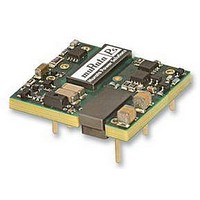
CONVERTER, DC/DC, 3.3V, 5A
Manufacturer
Murata Power Solutions Inc
Series
UEI15r
Datasheet
1.UEI15-050-Q48P-C.pdf
(12 pages)
Specifications of UEI15-033-Q48P-C
No. Of Output Channels
1
Input Voltage
18V To 75V
Power Rating
16.5W
Output Voltage
3.3V
Output Current
5A
Supply Voltage
48V
Dc / Dc Converter Case Style
Through Hole
Isolation Voltage
2.25kV
No. Of Outputs
1
Approval Bodies
CAN / CSA / EN / IEC / UL
Rohs Compliant
Yes
Product
Isolated
Output Power
16.5 W
Input Voltage Range
18 V to 75 V
Input Voltage (nominal)
48 V
Number Of Outputs
1
Output Voltage (channel 1)
3.3 V
Output Current (channel 1)
5 A
Package / Case Size
0.96 in x 1.1 in x 0.32 in
Output Type
Isolated DC/DC Converters
Lead Free Status / RoHS Status
Lead free / RoHS Compliant


Trim Equations
tor tolerances and factory-adjusted output accuracy. Mount trim resistor close
to converter. Use short leads.
Remote On/Off Control
On the input side, a remote On/Off Control can be ordered with either polarity.
is pulled high to +V
open pin to rise to +V
voltages (see Specifications). Positive-polarity devices are disabled when the
On/Off is grounded or brought to within a low voltage (see Specifications) with
respect to –V
Where Vo = Desired output voltage. Adjustment accuracy is subject to resis-
Positive: Standard models are enabled when the On/Off pin is left open or
R
R
R
R
T UP
T UP
T UP
T UP
() =
() =
() =
() =
IN
Figure 7 – Driving the Positive Polarity On/Off Control Pin
Trim and −V
resistor between
.
<Connect trim
Trim Up
V
12775
V
V
25000
25000
O
V
12775
IN
O
O
– 3.3
O
– 12
– 15
with respect to –V
IN
– 5
. Some models will also turn on at lower intermediate
OUT
>
– 2050
– 2050
– 5110
– 5110
UEI15-033-Q12, Q48
UEI15-050-Q12, Q48
UEI15-120-Q12, Q48
UEI15-150-Q12, Q48
IN
. An internal bias current causes the
R
R
R
R
T DOWN
T DOWN
T DOWN
T DOWN
CONTROL
-INPUT
ON/OFF
() =
() =
() =
() =
Trim and +V
resistor between
www.murata-ps.com
<Connect trim
Trim Down
5110 (Vo - 2.5)
5110 (Vo - 2.5)
10000 (Vo-2.5)
10000 (Vo-2.5)
3.3 – V
12 – V
15 – V
5 – V
OUT
>
O
O
O
O
– 2050
– 2050
– 5110
– 5110
Special Note for Low Noise Circuits
In order to achieve their extraordinary high efficiency and low heat dissipa-
tion, DC/DC converters by necessity have small residual switching noise
in their outputs. Generally this switching noise is at hundreds of kilohertz
therefore it can be extensively filtered. For circuits which are sensitive to this
kind of noise, multipole L-C passive filters are an effective solution. Be sure
to size the inductors to stay well below magnetic saturation and temperature
rise at the maximum operating current. Please refer to MPS’s FLT series
passive filters.
Off is grounded or brought to within a low voltage (see Specifications) with
respect to –V
pulled high to +15V
signal current when brought low and withstand appropriate voltage when
brought high. Be aware too that there is a finite time in milliseconds (see
Specifications) between the time of On/Off Control activation and stable,
regulated output. This time will vary slightly with output load type and current
and input conditions.
put side ONLY. If you must control it from circuits in the output, use some form
of optoisolation to the On/Off Control. This latter condition is unlikely because
the device controlling the On/Off would have to remain powered on and not be
powered from the converter.
carefully observe the voltage levels, the preferred circuit is either an open
drain/open collector transistor, a switch or a relay (which can thereupon be
controlled by logic). The On/Off prefers to be set at +V
ON state, assuming positive logic.
power voltage. Otherwise the converter may be permanently damaged.
Negative: Optional negative-polarity devices are on (enabled) when the On/
Dynamic control of the On/Off function should be able to sink appropriate
There are three CAUTION’s for the On/Off Control:
CAUTION: To retain full output circuit isolation, control the On/Off from the in-
CAUTION: While it is possible to control the On/Off with external logic if you
CAUTION: Do not apply voltages to the On/Off pin when there is no input
Isolated Wide Input Range 15-Watt DC/DC Converters
Figure 8 – Driving the Negative Polarity On/Off Control Pin
IN
. The device is off (disabled) when the On/Off is left open or is
dc
Technical enquiries email: sales@murata-ps.com, tel:
max. with respect to –V
IN
UEI15 Series
.
-INPUT
CONTROL
ON/OFF
MDC_UEI15W.B12 Page 9 of 12
IN
(open pin) for the
+1 508 339 3000
Related parts for UEI15-033-Q48P-C
Image
Part Number
Description
Manufacturer
Datasheet
Request
R

Part Number:
Description:
CONV DC/DC 16.5W 3.3V 5A
Manufacturer:
Murata Power Solutions Inc
Datasheet:

Part Number:
Description:
CONV DC/DC 14.85W 3.3V 4.5A
Manufacturer:
Murata Power Solutions Inc
Datasheet:

Part Number:
Description:
DC/DC
Manufacturer:
Murata Power Solutions Inc
Datasheet:
Part Number:
Description:
9-36Vin, 3.3Vout, 15W Negative Logic, SMT, RoHS
Manufacturer:
Murata Power Solutions Inc
Datasheet:
Part Number:
Description:
18-75Vin, 3.3Vout, 15W Positive Logic, SMT, RoHS
Manufacturer:
Murata Power Solutions Inc
Part Number:
Description:
DC/DC Converters & Regulators 16.5W 48Vin 3.3Vout 5A Neg Polarity SMT
Manufacturer:
Murata Power Solutions Inc
Datasheet:
Part Number:
Description:
DC/DC Converters & Regulators 14.85W 24Vin 3.3Vout 4.5A Pos Plrity SMT
Manufacturer:
Murata Power Solutions Inc
Datasheet:

Part Number:
Description:
POWER OVER ETHERNET MODULE
Manufacturer:
Murata Power Solutions Inc
Datasheet:

Part Number:
Description:
POWER OVER ETHERNET MODULE
Manufacturer:
Murata Power Solutions Inc
Datasheet:

Part Number:
Description:
POWER OVER ETHERNET MODULE
Manufacturer:
Murata Power Solutions Inc
Datasheet:

Part Number:
Description:
DC/DC TH Q12-15V UEI
Manufacturer:
Murata Power Solutions Inc
Datasheet:

Part Number:
Description:
Transformers 5Vin 5Vout 200mA 4000Vdc 1:1.33 turn
Manufacturer:
Murata Power Solutions Inc
Datasheet:

Part Number:
Description:
POWER SUPPLY
Manufacturer:
Murata Power Solutions Inc
Datasheet:

Part Number:
Description:
DPM LED MINI 2VDC 3.5DIG LP RED
Manufacturer:
Murata Power Solutions Inc
Datasheet:

Part Number:
Description:
CONV DC/DC 1W 5VIN 5VOUT SIP SGL
Manufacturer:
Murata Power Solutions Inc
Datasheet: