NFS110-7612J ARTESYN, NFS110-7612J Datasheet - Page 2
NFS110-7612J
Manufacturer Part Number
NFS110-7612J
Description
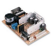
PSU, OPEN FRAME, 1 OUTPUT, 12V, 110W
Manufacturer
ARTESYN
Datasheet
1.NFS110-7612J.pdf
(3 pages)
Specifications of NFS110-7612J
Power Supply Type
Switch Mode
Power Supply Output Type
Fixed
No. Of Output Channels
1
Input Frequency
440Hz
Output Voltage
12V
Output Current
7A
Power Rating
110W
Input Voltage
85VAC To
No. Of Outputs
1
Rohs Compliant
Yes
Lead Free Status / RoHS Status
Lead free / RoHS Compliant


NFS110 Series
N N o o t t e e s s
1
2
3
4
5
6
7
8
9
10
11
12
13
14
15
For the most current data and application support visit www.artesyn.com/powergroup/products.htm
LOW TO MEDIUM POWER AC/DC POWER SUPPLIES
+24 V (I
Convection cooled, 80 W maximum.
Peak outputs lasting less than 60 seconds with duty cycle less than 10%.
Total peak power must not exceed 110 W.
Forced air, 20 CFM at 1 atmosphere, 110 W maximum.
Figure is peak-to-peak. Output ripple is measured across a 50 MHz
bandwidth using a 12 inch twisted pair terminated with a 47 µF capacitor.
Total regulation is defined as the static output regulation at 25 °C, including
initial tolerance, line voltage within stated limits and output voltages
adjusted to their factory settings.
To achieve stated regulation on the 24 V output on the NFS110-7602PJ,
the following load condition must be true: I
I
I
The +24 V output will maintain ±5.0% regulation under the following
additional condition: I
Single output models have floating outputs which may be referenced as
either positive or negative. Higher voltage supplies may be adjusted over a
wide output voltage range, as long as the total output power does not
exceed 80 Watts (natural convection) or 110 Watts (forced air).
Power fail detect not available on single output models.
Derating curve is application specific for ambient temperatures >50 °C, for
optimum reliability no part of the heatsink should exceed 90 ºC and no
semiconductor case temperature should exceed 100 ºC.
Caution: Allow a minimum of 1 second after disconnecting the power when
making thermal measurements.
Three orthogonal axes, random vibration, 10 minute test for each axis.
This product is only for inclusion by professional installers within other
equipment and must not be operated as a stand alone product.
Artesyn Technologies recommends a minimum load of 11 W to achieve the
design MTBF. See the derating curve on page 3.
The ‘J’ suffix indicates that these parts are Pb-free (RoHS 6/6) compliant.
TSE RoHS 5/6 (non Pb-free) compliant versions may be available on
special request, please contact your local sales representative for details.
NOTICE: Some models do not support all options. Please contact your
local Artesyn representative or use the on-line model number search tool at
http://www.artesyn.com/powergroup/products.htm to find a suitable
alternative.
A
B
VOLTAGE
+5.1 V (I
OUTPUT
= +5.1 V output current, and
= +24 V output current
+5.1 V
+5.1 V
+12 V
+12 V
+15 V
–12 V
–12 V
–15 V
5.1 V
–5 V
–5 V
12 V
15 V
24 V
B
)
A
(6)
)
S i n g l e a n d q u a d o u t p u t
A
≤ 5 A.
MAX
4.5 A
0.5 A
0.5 A
3.5 A
4.5 A
0.5 A
0.5 A
0.5 A
3.5 A
16 A
8 A
8 A
8 A
4 A
7 A
5 A
(1)
OUTPUT CURRENTS
A
/ I
PEAK
B
1.5 A
1.5 A
4.5 A
1.5 A
7.5 A
1.5 A
1.5 A
7.3 A
4.5 A
20 A
20 A
20 A
22 A
9 A
9 A
9 A
≤ 5, where:
(2)
FAN
4.5 A
7.3 A
4.5 A
80-110 W AC/DC Universal Input Switch Mode Power Supplies
10 A
10 A
10 A
20 A
5 A
1 A
1 A
5 A
1 A
5 A
1 A
1 A
9 A
(3)
TRANSIENT RESPONSE
NFS110-7601PJ
NFS110-7602PJ
NFS110-7604PJ
NFS110-7605J
NFS110-7612J
NFS110-7615J
NFS110-7624J
RIPPLE
120 mV
120 mV
240 mV
120 mV
120 mV
150 mV
150 mV
120 mV
150 mV
240 mV
50 mV
50 mV
50 mV
50 mV
50 mV
50 mV
(4)
REGULATION
+10/–5.0%
+5.1 V (7.5 A to 10 A)
+12 V (2.5 A to 5 A)
-12 V (0.5 A to 1 A)
-5 V (0.5 A to 1 A)
+5.1V (7.5 A to 10 A)
+24 V (1.5 A to 3 A)
+12 V (2.5 A to 5 A)
-12 V (0.5 A to 1 A)
+5.1 V (7.5 A to 10 A)
+15 V (2.5 A to 5 A)
-15 V (0.5 A to 1 A)
-5 V (0.5 A to 1 A)
+5.1 V (10 A to 20 A)
+12 V (4.5 A to 9 A)
+15 V (3.65 A to 7.3 A)
+24V (2.25 A to 4.5 A)
TOTAL
±2.0%
±3.0%
±3.0%
±3.0%
±2.0%
±3.0%
±3.0%
±2.0%
±3.0%
±3.0%
±3.0%
±2.0%
±2.0%
±2.0%
±2.0%
File Name: nfs110.pdf nls110.pdf Rev: 15 May 2006
(5)
MODEL NUMBERS
NFS110-7602PJ
NFS110-7605J
NFS110-7612J
NFS110-7615J
NFS110-7624J
NFS110-7601PJ
NFS110-7604PJ
0.5 ms recovery
0.5 ms recovery
0.5 ms recovery
0.5 ms recovery
0.5 ms recovery
0.5 ms recovery
0.5 ms recovery
0.5 ms recovery
1 ms recovery
1 ms recovery
1 ms recovery
1 ms recovery
1 ms recovery
1 ms recovery
1 ms recovery
1 ms recovery
150 mV peak,
100 mV peak,
100 mV peak,
100 mV peak,
150 mV peak,
300 mV peak,
100 mV peak,
100 mV peak,
100 mV peak,
100 mV peak,
100 mV peak,
360 mV peak,
720 mV peak,
150 mV peak,
250 mV peak,
450 mV peak,
(7,8)
(7,8)
(7,8)
(7,8)
(13,14,F)
(6)
2
Related parts for NFS110-7612J
Image
Part Number
Description
Manufacturer
Datasheet
Request
R

Part Number:
Description:
AC/DC Power Supply Single-OUT 12V 7A 110W 16-Pin
Manufacturer:
ARTESYN
Datasheet:

Part Number:
Description:
PSU, OPEN FRAME, 1 OUTPUT, 24V, 110W
Manufacturer:
ARTESYN
Datasheet:
Part Number:
Description:
AC/DC Power Supply Quad-OUT 5.1V/12V/-12V/-5V 8A/4.5A/0.5A/0.5A 110W 15-Pin
Manufacturer:
ARTESYN
Datasheet:
Part Number:
Description:
AC/DC Power Supply Quad-OUT 5.1V/15V/-15V/-5V 8A/4A/0.5A/0.5A 110W 15-Pin
Manufacturer:
ARTESYN
Datasheet:
Part Number:
Description:
AC/DC Power Supply Quad-OUT 5.1V/24V/12V/-12V 8A/3.5A/4.5A/0.5A 110W 16-Pin
Manufacturer:
ARTESYN
Datasheet:

Part Number:
Description:
Artesyn Technologies [Single output]
Manufacturer:
Artesyn Technologies
Datasheet:
Part Number:
Description:
Artesyn Technologies [8-10W Wide Input DC/DC Converters]
Manufacturer:
Artesyn Technologies
Part Number:
Description:
Artesyn Technologies [3W Wide Input DC/DC Converters]
Manufacturer:
Artesyn Technologies
Part Number:
Description:
Artesyn Technologies [100-150W Wide Input DC/DC Converters]
Manufacturer:
Artesyn Technologies
Part Number:
Description:
Artesyn Technologies [Single output]
Manufacturer:
Artesyn Technologies
Part Number:
Description:
Artesyn Technologies [66-100W Wide Input DC/DC Converters]
Manufacturer:
Artesyn Technologies
Part Number:
Description:
Artesyn Technologies [33-50W Wide Input DC/DC Converters]
Manufacturer:
Artesyn Technologies
Part Number:
Description:
357-036-542-201 CARDEDGE 36POS DL .156 BLK LOPRO
Manufacturer:
Artesyn Technologies
Datasheet:
Part Number:
Description:
Single and triple output 40 Watt Wide input DC/DC converters
Manufacturer:
Artesyn Technologies
Datasheet:
Part Number:
Description:
Single and dual output 20 Watt Wide input DC/DC converters
Manufacturer:
Artesyn Technologies
Datasheet: