S8VM05024C Omron, S8VM05024C Datasheet
S8VM05024C
Specifications of S8VM05024C


Related parts for S8VM05024C


S8VM05024C Summary of contents
Page 1
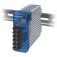
... Switch Mode Power Supply S8VM (15/30/50/100/150/300/600/1,500-W Models) Power Supply Featuring OMRON’s Unique, New Undervoltage Alarm Function with Compact Body Contributing to Machine Downsizing • New undervoltage alarm function assists in determining causes of errors (S8VM-@@@24A@/P@ only). • Power failure alarm function provides notification of output voltage errors (300-, 600-, and 1,500-W models only). ...
Page 2
... Ordering Information ■ List of Models Note: For details on normal stock models, contact your nearest OMRON representative. Configura- Power Input voltage Output voltage tion ratings Open-frame 15 W 100 to 240 VAC 5 V type 100 150 Covered 15 W 100 to 240 VAC 5 V type 100 W ...
Page 3
Specifications ■ Ratings/Characteristics Item Power rating Efficiency 5-V models 12-V models 15-V models 24-V models Input Voltage (See note 1.) Frequency (See note 1.) Current 100-V input 200-V input Power factor 100-V input 200-V input Harmonic current emissions Leakage 100-V ...
Page 4
Item Power rating Efficiency 5-V models 12-V models 15-V models 24-V models Input Voltage (See note 1.) Frequency (See note 1.) Current 100-V input 200-V input Power factor 100-V input 200-V input Harmonic current emissions Leakage current 100-V input 200-V ...
Page 5
Connections ■ Block Diagrams S8VM-015@@@@ ( (L) Fuse Noise 2 A INPUT filter AC (N) /FG S8VM-030@@@@ ( (L) Fuse Noise INPUT 3.15 A filter AC (N) /FG S8VM-050@@@@ ( (L) Fuse Noise 2 ...
Page 6
S8VM-100@@@@ (100 W) Inrush Harmonic current current protection Rectification suppression circuit AC (L) Fuse Noise INPUT 3.15 A filter AC (N) Drive Drive control circuit Overcurrent detection circuit /FG S8VM-150@@@@ (150 W) Inrush Harmonic current current protection Rectification suppression circuit ...
Page 7
S8VM-600@@C (600 W) AC (L) Noise Fuse INPUT filter (N) Rectification Rectifier/smoothing circuit Auxiliary power supply circuit Rectifier/smoothing circuit S8VM-15224C (1,500 W) Inrush current protection circuit AC (L) Fuse Noise INPUT 30 A filter AC (N) Rectifier/smoothing ...
Page 8
Construction and Nomenclature ■ Nomenclature 15-W, 30-W, 50-W Models Open-frame Models Covered Models S8VM-015@@/S8VM-015@@D S8VM-015@@C@/S8VM-01524A@ S8VM-030@@/S8VM-030@@D S8VM-030@@C@/S8VM-03024A@ S8VM-050@@/S8VM-050@@D S8VM-050@@C@/S8VM-05024A@/ 100-W Models Open-frame Models Covered Models S8VM-100@@/S8VM-100@@D S8VM-100@@C@/S8VM-10024A@/ ...
Page 9
Engineering Data (15-W, 30-W, 50-W, 100-W, 150-W Models) ■ Derating Curve 15W/30W Standard Mounting/Horizontal Mounting/Face-up Mounting 120 Open-frame type 100 A 80 Covered type −20 − Ambient ...
Page 10
Mounting Standard Mounting Standard Mounting (Bottom Mounting Models) (DIN Rail Mounting Bracket Models) Correct Correct Horizontal Mounting Correct *1 Face-up Mounting Face-up Mounting (DIN Rail Mounting Bracket Models) Incorrect Correct Face-down Mounting Face-down Mounting (DIN Rail Mounting Bracket Models) ...
Page 11
Overload Protection The Power Supply is provided with an overload protection function that protects the Power Supply from possible damage by short-circuit and overcurrent. When the output current rises above 105% min. of the rated current, the protection function ...
Page 12
... Probable Causes of Power Supply Errors and Troubleshooting Using Undervoltage Alarm Function Check the following information if the Undervoltage Alarm Function operates. Contact your OMRON representative if the Power Supply does not function normally after checking. The symbols in the table are as follows: : Lit, ...
Page 13
Probable cause of error --- A momentary power failure has occurred in the input. A momentary overload has occurred. A momentary output voltage drop has occurred at startup due to the capacity of the capacitive factors on the load side ...
Page 14
Construction and Nomenclature ■ Nomenclature 300-W Models S8VM-300@@C 600-W Models S8VM-600@@C 1,500-W Model S8VM-15224C ■ Output Color Label This color label identifies the output voltage by color. Color label identifying output voltage Note: A 300-W model is shown above. The ...
Page 15
Engineering Data (300-W, 600-W, 1,500-W Models) ■ Derating Curve 300W/600W/1,500W 120 100 −20 − Ambient temperature (°C) Note: 1. Internal parts may occasionally be deteriorated or dam- aged. Do ...
Page 16
Remote Control Function This function turns outputs ON and OFF using an external signal while input voltage is applied, using the +RC pin (pin 7 on CN) and the -RC pin (pin 8 on CN). Connect a switch or ...
Page 17
S8VM-600@@C 100 VAC, Load ratio: 100% 100 ms AC input current (10 A/DIV) Output voltage AC input voltage 200 VAC, Load ratio: 100% 100 ms AC input current (10 A/DIV) Output voltage AC input voltage S8VM-15224C 100 VAC, Load ratio: ...
Page 18
Overvoltage Protection Consider the possibility of an overvoltage and design the system so that the load will not be subjected to an excessive voltage even if the feedback circuit in the Power Supply fails. When an excessive volt- age ...
Page 19
Dimensions Note: All units are in millimeters unless otherwise indicated. ■ Bottom Mounting Models S8VM-015@@ S8VM-015@@C S8VM-01524A 8.5±0.5 Two, M3 (depth: 8 max.) Note: The image is the S8VM-01524 Model. 8.5±0.5 Two, M3 (depth: 8 max.) Note: The image is ...
Page 20
S8VM-050@@ S8VM-050@@C S8VM-05024A S8VM-05024P 68±0.5 8.5±0.5 Two, M3 (depth: 8 max.) 23.5±0.3 15±0.2 8±0.2 Note: The image is the S8VM-05024 Model. 68±0.5 8.5±0.5 Two, M3 (depth: 8 max.) 23.5±0.3 15±0.2 8±0.2 Note: The image is the S8VM-05024A Model. S8VM-100@@ S8VM-100@@C ...
Page 21
S8VM-150@@ S8VM-150@@C S8VM-15024A S8VM-15024P 68±0.5 8.5±0.5 Two, M3 (depth: 8 max.) 8.5±0.5 26.5±0.2 15±0.2 7.5±0.2 25±0.5 Note: The image is the S8VM-15024 Model. 68±0.5 8.5±0.5 Two, M3 (depth: 8 max.) 8.5±0.5 26.5±0.2 15±0.2 7.5±0.2 25±0.5 Note: The image is the ...
Page 22
DIN Rail Mounting Bracket Models S8VM-015@@D S8VM-015@@CD S8VM-01524AD Note: The image is the S8VM-01524D Model. Note: The image is the S8VM-01524AD Model. S8VM-030@@D S8VM-030@@CD S8VM-03024AD Note: The image is the S8VM-03024D Model. Note: The image is the S8VM-03024AD Model. ...
Page 23
S8VM-050@@D S8VM-050@@CD S8VM-05024AD S8VM-05024PD Note: The image is the S8VM-05024D Model. Note: The image is the S8VM-05024AD Model. S8VM-100@@D S8VM-100@@CD S8VM-10024AD S8VM-10024PD Note: The image is the S8VM-10024D Model. Note: The image is the S8VM-10024AD Model. 17.6 max. 14 120.5 ...
Page 24
S8VM-150@@D S8VM-150@@CD S8VM-15024AD S8VM-15024PD Note: The image is the S8VM-15024D Model. Note: The image is the S8VM-15024AD Model. 14 17.6 max. 160.5 82.5 170.4 5.4 (Sliding: 9 max.) 15 max. 14 164.5 84.5 46.2 174.4 5.4 (Sliding: 9 max.) S8VM ...
Page 25
Bottom Mounting Models S8VM-300@@C Four, M4 (depth: 6 max.) 60±0.5 11 10.5 40±0.5 Note: The image is the S8VM-30024C Model. S8VM-600@@C Four, M5 terminal screws 101.8 Three, M4 terminal screws Note: The image is the S8VM-60024C Model. S8VM-15224C Two, ...
Page 26
Mounting Brackets Mounting Bracket A (bottom mounting for 15-, 30-, and 50-W models) Mounting Bracket B (bottom mounting for 100- and 150-W models) Mounting Bracket C (front mounting for 15-, 30-, 50-, 100-, and 150-W models) Mounting Bracket D ...
Page 27
Mounting Bracket C (Front Mounting for 15-, 30- 50-, 100-, and 150-W Models) S82Y-VM10F Mounting Bracket D (Bottom Mounting for 300-W Models) S82Y-VM30B 60 5 195 Using the ...
Page 28
Mounting Bracket E (Horizontal Bottom Mounting for 300-W Models) S82Y-VM30S 8 6 Three, 4.5 dia. Mounting Bracket F (Front Mounting for 300-W Models) S82Y-VM30F Two, 4.5 dia 102.3 105 13.5 4.5 67 Using the Mounting Bracket 84 ...
Page 29
Mounting Bracket G (DIN Rail Mounting for 300-W Models) S82Y-VM30D 60 102.3 67 6.6 (Sliding: 12 max.) Note: Use a metal DIN Rail when mounting a 300-W model to a DIN Rail. Mounting Bracket H (Bottom Mounting for 600-W Models) ...
Page 30
Mounting Bracket J (Front Mounting for 600-W Models) S82Y-VM60F Two, 4.5 dia 102.3 105 13.5 4.5 105 Mounting Bracket K (DIN Rail Mounting for 600-W Models) S82Y-VM60D 98 102.3 105 6.6 (Sliding: 12 max.) Note: Use a ...
Page 31
Other Items Sold Separately Undervoltage Alarm Output Wiring Cable Signal I/O Connector Terminals and Housing Set contains ten SPHD-001T-P0.5 Terminals and one PHDR-12VS Housing. Replacement Fan Unit for 300-W Models Replacement Fan Unit for 600-W Models Replacement Fan Unit ...
Page 32
Safety Precautions Refer to Safety Precautions for All Power Supplies. !CAUTION Minor electric shock, fire, or Product failure may occasionally occur. Do not disassemble, modify, or repair the Product or touch the interior of the Product. Minor burns may occasionally ...
Page 33
Use the following material for the wires to be connected to the S8VM to prevent smoking or ignition caused by abnormal loads. Over heating or fire can result from inadequately sized wiring materials when problems occur at the load. As ...
Page 34
Insulation Test When performing the test, be sure to short-circuit all the output terminals to protect them from damage. Inrush Current When two or more Power Supplies are connected to the same input, inrush current is added to the total ...
Page 35
... Check if the +RC and -RC pins are open. Make the correct connec- tions as specified. Fan Replacement 300/600/1,500-W Models Consult with OMRON regarding fan replacement. OMRON will replace fans for a fee. A replacement Fan Unit (S82Y-VM@@FAN) is available. Use the curve in the graph below as a rough measure of replacement timing. ...
Page 36
ALL DIMENSIONS SHOWN ARE IN MILLIMETERS. To convert millimeters into inches, multiply by 0.03937. To convert grams into ounces, multiply by 0.03527. In the interest of product improvement, specifications are subject to change without notice. S8VM 36 ...
Page 37
... Please read and understand this catalog before purchasing the products. Please consult your OMRON representative if you have any questions or comments. WARRANTY OMRON's exclusive warranty is that the products are free from defects in materials and workmanship for a period of one year (or other period if specified) from date of sale by OMRON. OMRON MAKES NO WARRANTY OR REPRESENTATION, EXPRESS OR IMPLIED, REGARDING NON-INFRINGEMENT, MERCHANTABILITY, OR FITNESS FOR PARTICULAR PURPOSE OF THE PRODUCTS ...