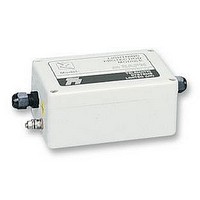
MSAPN MTL SURGE TECHNOLOGIES, MSAPN Datasheet - Page 2

MSAPN
Manufacturer Part Number
MSAPN
Description
LINE TRANSIENT BARRIER
Manufacturer
MTL SURGE TECHNOLOGIES
Series
MSAr
Datasheet
1.MSAPN.pdf
(2 pages)
Specifications of MSAPN
Suppressor Type
Data Line
Voltage Rating
180V
Operating Voltage Range
180VAC To 200VAC
Peak Surge Current
10kA
Connector Type
IDC Terminal
Clamping Voltage
200V
Clamping Voltage Vc Max
200V
Svhc
No SVHC (15-Dec-2010)
Specification
All figures typical at 25°C (77°F) unless otherwise stated
Maximum surge current
Nominal resistance per line
Ambient temperature limits
Humidity
Enclosure
Connectors
Terminals
Mounting
Weight
Dimensions
EMC compliance
R&TTE compliance
LVD compliance (mSAPN)
Installation
Figure 2 shows the installation for a typical
telemetry outstation. All cables entering the
telemetry cabin should be fitted with surge
protection devices (SPDs) to prevent lightning
currents entering telemetry equipment. mSA30
devices can be used for 4-20mA applications whilst
PSTN lines should be protected using the mSAPN.
Correct earthing is essential for optimum
protection against lightning induced overvoltages.
The units should be bonded to the incoming mains
power supply using a short length, preferably less
than 1 metre, of 2.5mm
Approvals
Note: Approvals now superseded by CE marking under the R&TTE
Directive. See ‘Specfication’ section for further information.
To order specify -
Note: In accordance with our policy of continuous improvement,
Telematic reserves the right to change the product’s specification
without notice.
MTL Surge Technologies
Power Court, Luton, Bedfordshire, England LU1 3JJ
Tel: +44 (0)1582 723633 Fax: +44 (0)1582 422283
E-mail: enquiry@mtlsurge.com WWW: www.mtlsurge.com
A member of the MTL Instruments Group plc
Model
mSA06 -
mSA51
mSAPN
10kA (8/20µs waveform)
mSA’s
mSAPN’s
-40°C to +80°C - working
-40°F to +176°F - working
5% to 95% RH (non-condensing)
Plastic ABS
IP65 (NEMA 12 and 13)
Ready fitted with cable glands
mSA’s
mSAPN’s
mSA’s
mSAPN’s
via M5 external earth stud
220g (7.8oz) approx.
See figure 1
To Generic Immunity Standards
BS EN 50082, part 2 for industrial
environments
BS EN 50082-2: 1995
BS EN 41003: 1999
BS EN 41003: 1999
Model number as per specification table above
Body
BT
Oftel
PTT
ODTR
43 ohms
5 ohms
screw-clamp terminals
IDC terminals
2.5mm
IDC terminals (tool provided)
Certificate
NS/2190/2/F/450911
NS/G/1235/W/100025
NL 93040203
(The Netherlands)
DOC 19/99 (Eire)
2
or greater thickness cable.
2
(12AWG)
Definitions of terminology used in table
1
2
Model
mSA06/1
mSA16/1
mSA30/1
mSA51/1
mSA75/1
mSA06/2
mSA16/2
mSA30/2
mSA51/2
mSA75/2
mSAPN/1
mSAPN/2
Figure 1 Dimensions
Figure 2 Installation and earthing for typical control systems
Working voltage
Maximum voltage between lines or lines/earth
for the specified leakage current
Maximum leakage current
Maximum current drawn by the SPD at the
working voltage
2 pairs
2 pairs
2 pairs
2 pairs
2 pairs
2 pairs
1 pair
1 pair
1 pair
1 pair
1 pair
1 pair
Lines
Working
voltage
25.5
43.5
25.5
43.5
13.5
13.5
180
180
(V)
5.5
5.5
64
64
current
Rated
(mA)
load
340
400
400
340
400
400
N/A
N/A
180
180
70
70
Maximum
leakage
current
1000
1000
3
4
(µA)
10
10
5
5
5
5
5
5
5
5
Maximum continuous operating voltage
Maximum voltage that can be applied to the
protected terminals without damage
Limiting voltage
Peak output voltage after injection of test impulse
from 6kV/3kA combination waveform generator
(often known as ‘let-through’ voltage)
continuous
Maximum
operating
voltage
200
200
(V)
30
75
30
75
16
51
16
51
6
6
Limiting
voltage
250
250
100
150
100
150
(V)
30
40
60
30
40
60
Bandwidth
220kHz
380kHz
500kHz
580kHz
600kHz
220kHz
380kHz
500kHz
580kHz
600kHz
10MHz
10MHz


