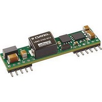
LSN2-T/16-D12G-C Murata Power Solutions Inc, LSN2-T/16-D12G-C Datasheet - Page 9

LSN2-T/16-D12G-C
Manufacturer Part Number
LSN2-T/16-D12G-C
Description
DC/DC Converter
Manufacturer
Murata Power Solutions Inc
Series
LSN2r
Datasheet
1.LSN2-T10-D12G-C.pdf
(15 pages)
Specifications of LSN2-T/16-D12G-C
No. Of Outputs
1
Input Voltage
8.3V To 14V
Power Rating
80W
Output Current
16A
Approval Bodies
UL, CSA
Supply Voltage
14VDC
Dc / Dc Converter Case Style
SIP
Dc/dc Converter Mounting
Through Hole
Product
Non-Isolated / POL
Output Power
80 W
Input Voltage Range
8.3 V to 14 V
Input Voltage (nominal)
12 V
Number Of Outputs
1
Output Voltage (channel 1)
0.75 V to 5 V
Output Current (channel 1)
16 A
Package / Case Size
SIP
Output Type
Low Voltage Selectable
Output Voltage
0.75 V to 5 V
Lead Free Status / RoHS Status
Lead free / RoHS Compliant
through forward biased ESD diodes. Conventional DC/DC’s may fail to start up
correctly if there is output voltage already present. And some external circuits
are adversely affected when the low side MOSFET in a synchronous rectifi er
converter sinks current at start up.
tion problems. Essentially, the converter acts as a simple buck converter until
the output reaches its set point voltage at which time it converts to a synchro-
nous rectifi er design. This feature is variously called “monotonic” because the
voltage does not decay (from low side MOSFET shorting) or produce a negative
transient once the input power is applied and the startup sequence begins.
Don’t Use Pre-Biasing and Sequencing Together
Normally, you would use startup sequencing on multiple DC/DC’s to solve the
Pre-Bias problem. By causing all power sources to ramp up together, no one
source can dominate and force the others to fail to start. For most applica-
tions, do not use startup sequencing in a Pre-Bias application, especially with
an external active power source.
that the output will step up quickly and safely. A symptom of this condition is
repeated failed starts. You can further verify this by removing the existing load
and testing it with a separate passive resistive load which does not exceed full
current. If the resistive load starts successfully, you may be trying to drive an
external pre-biased active source.
Bias source is in fact only a small external bypass capacitor slowly charged by
leakage currents. Test your application to be sure.
Output Adjustments
The LSN2 series includes a special output voltage trimming feature which
is fully compatible with competitive units. The output voltage may be varied
using a single trim resistor from the Trim input to Power Common (pin 4) or an
external DC trim voltage applied between the Trim input and Power Common.
The output voltage range for W3 models is 0.75 to 3.3 Volts. For D12 models,
the output range is 0.75 to 5 Volts.
3.3 Volts maximum, the input supply must be 4.5 Volts minimum. To retain
proper regulation, do not exceed the 3.3V output.
resistor (±100 ppm/°C) mounted close to the converter with short leads. Also
be aware that the output voltage accuracy is ±2% (typical) therefore you may
need to vary this resistance slightly to achieve your desired output setting.
W3 Models Resistor Trim Equation:
V
R
The LSN2 series includes a pre-bias startup mode to prevent these initializa-
If you have active source pre-biasing, leave the Sequence input open so
It may also be possible to use pre-bias and sequencing together if the Pre-
IMPORTANT: On W3 models only, for outputs greater than 3 Volts up to
As with other trim adjustments, be sure to use a precision low-tempco
Two different trim equations are used for the W3 and D12 models.
The W3 models fi xed trim resistors to set the output voltage are:
OUT
TRIM
(Typ.) 0.7525V
R
(kΩ)
TRIM
(:) = _____________ – 5110
Open
V
80.021 41.973 23.077 15.004 6.947
O
1.0V
21070
– 0.7525
1.2V
1.5V
1.8V
2.5V
www.murata-ps.com
3.3V
3.16
D12 Models Resistor Trim Equation:
Voltage Trim
The LSN2 Series may also be trimmed using an external voltage applied
between the Trim input and Output Common. Be aware that the internal “load”
impedance looking into trim pin is approximately 5k:. Therefore, you may
have to compensate for this in the source resistance of your external voltage
reference.
converter.
W3 Models Voltage Trim Equation:
D12 Models Voltage Trim Equation:
LSN2 Power Sequencing
Whereas in the old days, one master switch simultaneously turned on the
power for all parts of a system, many modern systems require multiple supply
voltages for different on-board sections. Typically the CPU or microcontroller
needs 1.8 Volts or lower. Memory (particularly DDR) may use 1.8 to 2.5 Volts.
Interface “glue” and “chipset” logic might use +3.3Vdc power while Input/
Output subsystems may need +5V. Finally, peripherals use 5V and/or 12V.
V
V
V
V
V
R
OUT
OUT
OUT
TRIM
TRIM
TRIM
Use a low noise DC reference and short leads. Mount the leads close to the
Two different trim equations are used for the W3 and D12 models.
The LSN2 W3 fi xed trim voltages to set the output voltage are:
The LSN2 D12 fi xed trim voltages to set the output voltage are:
(Typ.) 0.7525V
(Typ.) 0.7525V 1.0V
(Typ.) 0.7525V
(kΩ)
R
TRIM
V
V
TRIM
TRIM
(:) = _____________ – 1000
Open
Open
Open
(in Volts) = 0.7 – (0.1698 x (V
(in Volts) = 0.7 – (0.0667 x (V
0.6928V 0.624V 0.5731V 0.5221V 0.4033V 0.267V
0.6835 0.670 0.650 0.630 0.583 0.530 0.4166
41.424 22.46 13.05 9.024 5.009 3.122 1.472
V
1.0V
1.0V
O
10500
– 0.7525
Figure 6. Trim Connections
Selectable-Output DC/DC Converters
1.2V
1.2V
1.2V
25 Jun 2010
Non-isolated, DOSA-SIP, 6/10/16A
1.5V
1.5V
1.5V
O
O
LSN2 Series
– 0.7525))
– 0.7525))
1.8V
email: sales@murata-ps.com
1.8V
MDC_LSN2.B07Δ
1.8V
2.5V
2.5V
2.5V
3.3V
3.3V
Page 9 of 15
3.3V
5V
5V


