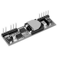
LSN-2.5/10-D12H-C Murata Power Solutions Inc, LSN-2.5/10-D12H-C Datasheet - Page 2

LSN-2.5/10-D12H-C
Manufacturer Part Number
LSN-2.5/10-D12H-C
Description
DC/DC Converter
Manufacturer
Murata Power Solutions Inc
Series
LSNr
Datasheet
1.LSN-2.510-D12-C.pdf
(12 pages)
Specifications of LSN-2.5/10-D12H-C
Dc / Dc Converter O/p Type
Fixed
No. Of Outputs
1
Input Voltage
10.8V To 13.2V
Power Rating
25W
Output Voltage
2.5V
Output Current
10A
Approval Bodies
EN, IEC, UL
Supply Voltage
12V
Product
Non-Isolated / POL
Output Power
25 W
Input Voltage Range
10 V to 14 V
Input Voltage (nominal)
12 V
Number Of Outputs
1
Output Voltage (channel 1)
2.5 V
Output Current (channel 1)
10 A
Package / Case Size
SIP
Output Type
Low Voltage Reversed Pin
Lead Free Status / RoHS Status
Lead free / RoHS Compliant
Performance Specifications and Ordering Guide
LSN-1/10-D12
LSN-1.1/10-D12
LSN-1.2/10-D12
LSN-1.3/10-D12
LSN-1.5/10-D12
LSN-1.8/10-D12
LSN-2/10-D12
LSN-2.5/10-D12
LSN-3.3/10-D12
LSN-3.8/10-D12
LSN-5/10-D12
(1.27)
Root Model
P A R T
0.05
(12.7)
Nominal Output Voltage:
DIMENSIONS IN INCHES (mm
0.50
Output
Configuration:
Note: Not all model number
combinations are available.
Contact Murata Power Solutions
1, 1.1, 1.2, 1.3, 1.5, 1.8, 2, 2.5, 3.3
or 5 Volts
Typical at T
models are tested and specified with external 22μF tantalum input and output capacitors. The
capacitors are necessary to accommodate our test equipment and may not be required to
achieve specified performance in your applications. See I/O Filtering and Noise Reduction.
Ripple/Noise (R/N) is tested/specified over a 20MHz bandwidth and may be reduced with
external filtering. See I/O Filtering and Noise Reduction for details.
L = Unipolar
ON PCB (0.55 SQ. IN.)
4 EQ. SP. @
0.100 (2.54)
1 2 3 4 5
Low Voltage
RECOMMENDED
(10.16)
(14.22)
0.400
Non-Isolated SIP
COPPER PAD
0.56
N U M B E R
A
= +25°C under nominal line voltage and full-load conditions, unless noted. All
Maximum Rated Output
Current in Amps
L SN
0.030 ±0.001 DIA.
(0.762 ±0.025)
(13.46)
(Volts)
0.53
V
1.1
1.2
1.3
1.5
1.8
2.5
3.3
3.8
OUT
(25.40)
)
1
2
5
1.000
(50.80)
2.00
-
1.8
S T R U C T U R E
LAYOUT PATTERN
(Amps)
TOP VIEW
I
10
10
10
10
10
10
10
10
10
10
10
OUT
/
6
5 EQ. SP. @
0.100 (2.54)
10
7
(12.70)
Input Voltage Range:
0.500
8 9
* Contact Murata Power Solutions Technologies
(DATEL) for availability.
D12 = 10.8 to 13.2 Volts (12V nominal)
-
10 11
D12 B
Typ.
45
45
45
45
30
30
30
35
40
40
50
R/N (mVp-p)
(13.97)
(13.97)
www.murata-ps.com
0.55
0.55
Output
(1.27)
0.05
B Suffix:
No Remote Sense (Pin 3 removed)
ISOLATING
Max.
H Suffix:
H
65
60
60
60
45
45
45
50
55
55
75
Horizontal Mounting
PAD
(8.89)
(5.33)
0.35
0.21
Horizontal Mount
J Suffix:
J
Case B5A
Reversed Pin
Vertical Mount
0.360
(9.14)
-
RoHS-6
compliant*
Regulation (Max.)
Pin
±0.1%
±0.1%
±0.1%
±0.1%
±0.1%
±0.1%
±0.1%
±0.1%
±0.1%
±0.1%
±0.1%
1
2
3
4
C
Line
Single Output, Non-Isolated, 12V
Function P59*
(4.06
0.16
+Sense *
+Output
+Output
+Output
±0.25%
±0.25%
±0.25%
±0.25%
±0.25%
±0.25%
±0.25%
±0.25%
±0.25%
±0.25%
±0.25%
Load
Pin
M E C H A N I C A L
V
5
6
7
8
(4.32)
(4.32)
(Volts)
0.17
0.17
IN
(6.35)
0.306
I/O Connections
0.25
These devices have no minimum-load requirements and will regulate under no-load conditions.
Regulation specifications describe the output-voltage deviation as the line voltage or load is
varied from its nominal/midpoint value to either extreme.
Nominal line voltage, no-load/full-load conditions.
These are not complete model numbers. Please refer to the Part Number Structure when
ordering.
(7.8)
12
12
12
12
12
12
12
12
12
12
12
Nom.
Function P59*
4 EQ. SP. @
0.100 (2.54)
4 EQ. SP. @
0.100 (2.54)
1 2 3 4 5
1 2 3 4 5
Common
Common
+Input
+Input
(10.16)
(10.16)
0.400
0.400
10.8-13.2
10.8-13.2
10.8-13.2
10.8-13.2
10.8-13.2
10.8-13.2
10.8-13.2
10.8-13.2
10.8-13.2
10.8-13.2
10.8-13.2
Range
(Volts)
Input
0.030 ±0.001 DIA.
0.030 ±0.001 DIA.
Technical enquiries email: sales@murata-ps.com, tel:
LAYOUT PATTERN
(0.762 ±0.025)
(0.762 ±0.025)
LAYOUT PATTERN
Pin
10
11
9
TOP VIEW
LSN-10A D12 Models
(25.40)
(mA/A)
TOP VIEW
(25.40)
1.000
(50.80)
(50.80)
1.000
39/1.02
45/1.19
54/1.47
53/1.75
69/3.33
45/1.1
45/1.3
59/1.9
60/2.3
75/4.5
I
IN
2.00
2.00
IN
S P E C I F I C A T I O N S
69/3
Function P59*
On/Off Control
, 1-5V
V
No Pin
OUT
Trim
88.5%
90.5%
92.5%
6
6
Min.
OUT,
83%
85%
85%
85%
86%
87%
93%
94%
5 EQ. SP. @
0.100 (2.54)
5 EQ. SP. @
0.100 (2.54)
7
7
(12.70)
Full Load
(12.70)
0.500
0.500
8 9 10 11
8 9 10 11
10A, DC/DC's in SIP Packages
Efficiency
* Pin 3 (+Sense) removed
90.5%
92.5%
Typ.
86%
88%
88%
88%
89%
91%
94%
95%
96%
MDC_LSN10A-D12.B01 Page 2 of 12
for "B" suffix models.
(13.97)
(13.97)
(8.64)
0.55
0.34
0.55
(9.14)
0.36
(1.27)
(1.27)
0.05
0.05
½ Load
87.5%
87.5%
87.5%
89.5%
93.5%
95.5%
Typ.
86%
88%
90%
92%
N/A
(8.64)
(5.08)
(9.14)
(5.08)
0.34
0.20
0.36
0.20
(Tyco-compatible)
Vertical Mounting
0.110
(2.79)
Vertical Mounting
(1.17)
0.046
(1.17)
0.046
Reverse Pin
0.106
(2.69)
Case B5B
(Standard)
Case B5
B5/B5x, P59
B5/B5x, P59
B5/B5x, P59
B5/B5x, P59
B5/B5x, P59
B5/B5x, P59
B5/B5x, P59
B5/B5x, P59
B5/B5x, P59
B5/B5x, P59
B5/B5x, P59
+1 508 339 3000
Package
Pinout)
(Case,


