MX19P10K451 JAE Electronics, MX19P10K451 Datasheet
MX19P10K451
Specifications of MX19P10K451


Related parts for MX19P10K451


MX19P10K451 Summary of contents
Page 1
Japan Aviation Electronics Industry, Ltd. Connector Division Title: Handling Manual for MX19 series connector Handling Manual Originating Dept.: Connector Div. 3rd Engineering Dept. Contents 1. Purpose 2. Applicable Items 3. Crimping 3-1. Applicable Wires 3-2. Stripping length of wire insulators ...
Page 2
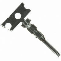
... Table2-1 MX19 Connector Housing Type Pin Housing Socket Housing Pin Housing Socket Housing Table2-2 MX19 Contacts and Dummy plug Product Name MX19P10K451 MX19S10K451 MX19000XD1 MX19002S5* Fig.2-4 Socket contact. JAE Connector Div. Proprietary. Copyright © 2000,Japan Aviation Electronics Industry, Ltd. JAHL-1594-E ...
Page 3
... Table3-2 Applicable Wire for MX19 connector Calc. Conductor of (No./Shape or size) cross-section [ mm 7/ φ0.13 7/ φ0.13 Cutoff Short length Fail Fail MX19P10K451 MX19S10K451 Wire JAE Connector Div. Proprietary. Copyright © 2000,Japan Aviation Electronics Industry, Ltd. JAHL-1594-E Semi-automatic Applicator 350-MX19-2 Wire Insulator [mm ...
Page 4
Japan Aviation Electronics Industry, Ltd. Connector Division 3.3 Part description 3.3.1 Pin Contact Conductor Barrel 3.3.2 Socket contact Conductor barrel 3.4 Criteria for conformed crimping items "Properly crimped contact" follows: 1. Meet the crimp height shown in Table ...
Page 5
Japan Aviation Electronics Industry, Ltd. Connector Division 3.4 Criteria for judgment on non-conforming items If a crimped MX19 contact has any following defective item, the crimping work is failure. DON’T use the failure crimping contact. Defective Item No. Incomplete wire ...
Page 6
Japan Aviation Electronics Industry, Ltd. Connector Division Defective Item No. Inclined Insulator Barrel The incline over 0.3mm at any side. 5 Bended( On axis) The angle “P” over 3 degrees, between 6 crimping parts axis. Twisted The angle of center ...
Page 7
Japan Aviation Electronics Industry, Ltd. Connector Division Defective Item No. Bend up/ down “Bend up(or down)” is based on the crimp barrel area. Failure case is dimension Y1 (or Y2) is over C1 ...
Page 8
Japan Aviation Electronics Industry, Ltd. Connector Division 4. Contact/ Dummy Plug Insertion 4.1 Contact Insertion 1. Visual inspection, the connector has no breakage, deformation, discoloration, and/or damage etc. 2. Aligned the axis and direction between a contact and a cavity. ...
Page 9
Japan Aviation Electronics Industry, Ltd. Connector Division △ 4.2 Dummy Plug Insertion 1. Check by visual inspection, the connector has no breakage, deformation, discoloration, and/or damage etc. 2. Aligned the axis between a dummy plug and a cavity. 3. Inserting ...
Page 10
Japan Aviation Electronics Industry, Ltd. Connector Division △ 5. Contact withdraw 2 1. Visual inspection, the connector has no breakage, deformation, discoloration, and/or damage etc. 2. Pushing lightly the wire with crimpling contact and keeping. 3. Inserting a “Withdrawing Tool” ...
Page 11
Japan Aviation Electronics Industry, Ltd. Connector Division 6. How to engage connector 6.1 Engaging 1. Check the contact insertion. 2. Check by visual inspection, the connector has no breakage, deformation, discoloration, and/or damage etc. in contacts and housing. 3. Aligned ...
Page 12
Japan Aviation Electronics Industry, Ltd. Connector Division 6.2 Connector Separation Method Hold a Socket Housing, and pull out the connector straightly; 1: Depressing the lock arm of socket housing. 2: Releasing the engagement lock. NOTE: On separating the connector, DON’T ...
Page 13
Japan Aviation Electronics Industry, Ltd. Connector Division 7. Cautionary Statements △ ! Comply strictly with the following matters because of possibility of physical damage and/or connector failures. ● Perform the engagement of connector straightly until the "click" sound. ● Be ...