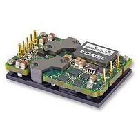
UQQ-3.3/25-Q12P-C Murata Power Solutions Inc, UQQ-3.3/25-Q12P-C Datasheet - Page 3

UQQ-3.3/25-Q12P-C
Manufacturer Part Number
UQQ-3.3/25-Q12P-C
Description
CONVERTER, DC/DC, WI, 82.5W
Manufacturer
Murata Power Solutions Inc
Series
UQQr
Type
Step Downr
Specifications of UQQ-3.3/25-Q12P-C
Output Type
Single
No. Of Output Channels
1
Input Voltage
9V To 36V
Power Rating
82.5W
Output Voltage
3.3V
Output Current
25A
Supply Voltage
12V
Dc / Dc Converter Case Style
Quarter Brick
Dc / Dc Converter O/p Type
Single
No. Of Outputs
1
Approval Bodies
EN / IEC / UL
Rohs Compliant
Yes
Product
Isolated
Output Power
83 W
Input Voltage Range
9 V to 36 V
Input Voltage (nominal)
12 V
Number Of Outputs
1
Output Voltage (channel 1)
3.3 V
Output Current (channel 1)
25 A
Isolation Voltage
2 KV
Package / Case Size
Quarter Brick
Screening Level
Industrial
Product Length (mm)
36.8mm
Product Height (mm)
10.9mm
Mounting Style
Through Hole
Pin Count
9
Lead Free Status / RoHS Status
Lead free / RoHS Compliant
Soldering Guidelines
Murata Power Solutions recommends the specifi cations below when installing these converters. These specifi cations vary depending on the solder type. Exceeding these specifi ca-
tions may cause damage to the product. Your production environment may differ; therefore please thoroughly review these guidelines with your process engineers.
CLEARANCE
For Sn/Ag/Cu based solders:
Maximum Preheat Temperature
Maximum Pot Temperature
Maximum Solder Dwell Time
MECHANICAL SPECIFICATIONS
Wave Solder Operations for through-hole mounted products (THMT)
BOTTOM
0.25
.010
MIN
BASEPLATE
END VIEW
WITH
C L
18.42
.725
REF
4.76
.187
3.81
.150
115° C.
270° C.
7 seconds
12.7
36.8
1.45
.50
BASEPLATE
OPTIONAL
'B' OPTION
3.81
.150
26.16
1.030
For Sn/Pb based solders:
Maximum Preheat Temperature
Maximum Pot Temperature
Maximum Solder Dwell Time
8
7
6
5
4
25.4
1.00
23.6
REF
.93
REF
2X
BOTTOM VIEW
AT PINS 4 & 8
SIDE VIEW
TOP VIEW
56.4
2.22
1.57±0.05
50.80
2.000
.062±.002
C L
C L
www.murata-ps.com
47.24
1.860
105° C.
250° C.
6 seconds
3
2
9
1
13.08
.515
REF
AT PINS 1-3, 5-7, (9)
1.02±0.05
Wide Input Range Single Output DC/DC Converters
.040±.002
C L
Optional pin #9
Connects to baseplate
And is electrically
isolated from converter
.300
ON EACH
4X M3X0.5
THRU , .10" MAX
PENETRATION
(4 PLS)
VENTED SHOULDER
7.62
10.9
.071±.002 [1.80]
.43
C L
.300
BASEPLATE
7.62
END VIEW
WITHOUT
.040 PIN
Dimensions are in inches (mm shown for ref. only).
Components are shown for reference only.
22 Feb 2011 MDC_UQQ.A15 Page 3 of 18
* These converters are pin-for-pin/plug-
** The Remote On/Off can be provided with
Tolerances (unless otherwise specified):
.XX ± 0.02 (0.5)
.XXX ± 0.010 (0.25)
Angles ± 2˚
compatible to competitive units. Other
units may use different pin numbering or
alternate outline views. When laying out
your PC board, follow the pin FUNCTION.
DOSA designates Pin 1 as +Input and Pin 3
as -Input.
either positive ("P" suffi x) or negative
("N" suffi x) polarity.
Important! Always connect the sense pins;
see Application Notes.
Standard pin length is shown. Please refer
to the Part Number Structure for alternate
pin lengths.
Pin
1
2
3
4
5
6
7
8
9
Input/Output Connections
email: sales@murata-ps.com
DOSA-Compatible
Third Angle Projection
UQQ Series
Baseplate (optional)
Remote On/Off**
Function P32
Output Trim
+Output
+Input*
-Output
+Sense
-Input*
-Sense


