UEI15-120-Q12N-C Murata Power Solutions Inc, UEI15-120-Q12N-C Datasheet - Page 5
UEI15-120-Q12N-C
Manufacturer Part Number
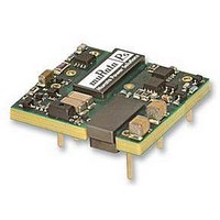
UEI15-120-Q12N-C
Description
CONVERTER, DC/DC, 12V, 1.3A
Manufacturer
Murata Power Solutions Inc
Series
UEI15r
Specifications of UEI15-120-Q12N-C
No. Of Output Channels
1
Input Voltage
9V To 36V
Power Rating
15.6W
Output Voltage
12V
Output Current
1.3A
Supply Voltage
24V
Dc / Dc Converter Case Style
Through Hole
Isolation Voltage
2.25kV
Product
Isolated
Output Power
15.6 W
Input Voltage Range
9 V to 36 V
Input Voltage (nominal)
24 V
Number Of Outputs
1
Output Voltage (channel 1)
12 V
Output Current (channel 1)
1.3 A
Package / Case Size
0.96 in x 1.1 in x 0.32 in
Output Type
Isolated DC/DC Converters
Lead Free Status / RoHS Status
Lead free / RoHS Compliant


Absolute Maximum Ratings
Absolute maximums are stress ratings. Exposure of devices to any of these
conditions may adversely affect long-term reliability. Proper operation under
conditions other than those listed in the Performance/Functional Specifications
is neither implied nor recommended.
table below. The external capacitors listed below are ONLY for establishing test
specifications. They are required for our test fixtures and equipment. Your applica-
tion may not need them. The converter is stable with no external capacitors but
Murata Power Solutions strongly recommends external caps. All caps are low-ESR
types. Where two or more capacitors are listed, these are connected in parallel. All
caps should mount close to the DC/DC using short leads.
tions are +25 deg.C, V
must be supplied for extended testing under power.
width. Input filtering is C
trolytic, L
ABSOLUTE MAXIMUM RATINGS
(1) All models are tested and specified with external capacitors listed in the
All specifications are typical unless noted. General conditions for Specifica-
(2) Input Ripple Current is tested and specified over a 5 Hz to 20 MHz band-
Input Reverse Polarity Protection
Output Overvoltage, Volts Max.
Output Current, sustained short circuit
Storage Temperature
Lead Temperature ºC Max. (soldering, 10 seconds)
Voltage
Input
referred to –V
On/Off control,
bus
Model
UEI15-033-Q12
UEI15-033-Q48
UEI15-050-Q12
UEI15-050-Q48
UEI15-120-Q12
UEI15-120-Q48
UEI15-150-Q12
UEI15-150-Q48
=12 µH.
Q12 models
Q48 models
INPUT/OUTPUT EXTERNAL TEST CAPACITORS
in
in
=nominal, V
in
=33 µF, 100V tantalum, C
SPECIFICATION NOTES
Volts, transient 100mS
Volts, transient 100mS
Volts Max. continuous
Volts Max. continuous
Range, Min. ºC
Max. ºC
Input Capacitor
4.7 µF ceramic
4.7 µF ceramic
4.7 µF ceramic
4.7 µF ceramic
out
Volts, Max.
Volts, Min.
100 µF
100 µF
100 µF
100 µF
=nominal, full load. Adequate airflow
www.murata-ps.com
bus
Output Capacitor(s)
Current-limited, see specs
=220 µF, 100V elec-
1 µF & 10 µF
1 µF & 10 µF
1 µF & 10 µF
1 µF & 10 µF
1 µF & 10 µF
1 µF & 10 µF
1 µF & 10 µF
1 µF & 10 µF
V
See fuse section
out
nom. +20%
+125
–0.3
100
280
-55
36
50
75
15
nominal input voltage. At higher temperatures and/or lower airflow, the DC/DC
converter will tolerate brief full current outputs if the total RMS current over time
does not exceed the Derating curve. All Derating curves are presented at sea level
altitude. Be aware of reduced power dissipation with increasing density altitude.
332 Method 1, Case 3, ground fixed conditions, Tpcboard=+25 deg.C, full load,
natural air convection.
driven with external logic or by applying appropriate external voltages which
are referenced to Input Common. The On/Off Control Input should use either an
open collector or open drain transistor.
approximately 2% from the selected setting.
may damage the outputs.
I/O Filtering and Noise Reduction.
including “cold start” at –40
on-board components must not exceed +128°C.
or output load current is varied from a nominal midpoint value to either extreme.
removal. The overvoltage may occur either from internal failure or from an
external forcing voltage as in a shared power system.
the overcurrent fault is removed, the converter will immediately recover.
output trim.
ponents which exceed the ripple specification. The output may be operated
indefinitely with no load.
will become forward biased and will conduct considerable current. To ensure
reverse input protection with full output load, always connect an external input
fuse in series with the +V
rent rating with nominal input voltage.
a brief, full-current output. If the overcurrent condition still exists, the restart
current will be removed and then tried again. This short current pulse prevents
overheating and damaging the converter. Once the fault is removed, the con-
verter immediately recovers normal operation.
agency certifications and to avoid injury to personnel or equipment, the user
must connect an external fast-blow fuse to the input terminals. See fuse
information.
(3) Note that Maximum Power Derating curves indicate an average current at
(4) Mean Time Before Failure is calculated using the Telcordia (Belcore) SR-
(5) The On/Off Control is normally controlled by a switch. But it may also be
(6) Output current limiting begins when the output voltage degrades
(7) The outputs are not intended to sink appreciable reverse current. This
(8) Output noise may be further reduced by adding an external filter. See
(9) All models are fully operational and meet published specifications,
(10) Regulation specifications describe the deviation as the line input voltage
(11) The output overvoltage protection is automatic recovery after fault
(12) Output current limit and short circuit protection is non-latching. When
(13) Do not exceed maximum power specifications when adjusting the
(14) At zero output current, the output may contain low frequency com-
(15) If reverse polarity is accidentally applied to the input, a body diode
(16) “Hiccup” operation repeatedly attempts to restart the converter with
CAUTION: This product is not internally fused. To comply with safety
Isolated Wide Input Range 15-Watt DC/DC Converters
Technical enquiries email: sales@murata-ps.com, tel:
in
input. Use approximately twice the full input cur-
0
C. At full power, the package temperature of all
UEI15 Series
MDC_UEI15W.B12 Page 5 of 12
+1 508 339 3000
Related parts for UEI15-120-Q12N-C
Image
Part Number
Description
Manufacturer
Datasheet
Request
R

Part Number:
Description:
CONV DC/DC 15.6W 12V 1.3A
Manufacturer:
Murata Power Solutions Inc
Datasheet:

Part Number:
Description:
CONV DC/DC 15.6W 12V 1.3A
Manufacturer:
Murata Power Solutions Inc
Datasheet:

Part Number:
Description:
9-36Vin, 12Vout, 15W Negative Logic, SMT, RoHS
Manufacturer:
Murata Power Solutions Inc
Datasheet:
Part Number:
Description:
DC/DC
Manufacturer:
Murata Power Solutions Inc
Datasheet:
Part Number:
Description:
18-75Vin, 12Vout, 15W Positive Logic, SMT, RoHS
Manufacturer:
Murata Power Solutions Inc
Datasheet:
Part Number:
Description:
DC/DC Converters & Regulators 15.6W 24Vin 12Vout 1.3A PosPolarity SMT
Manufacturer:
Murata Power Solutions Inc
Datasheet:
Part Number:
Description:
DC/DC Converters & Regulators 15.6W 48Vin 12Vout 1.3A NegPolarity SMT
Manufacturer:
Murata Power Solutions Inc
Datasheet:

Part Number:
Description:
CONV DC/DC 15W 5V 3A
Manufacturer:
Murata Power Solutions Inc
Datasheet:

Part Number:
Description:
CONVERTER, DC/DC, 5V, 3A
Manufacturer:
Murata Power Solutions Inc
Datasheet:
Part Number:
Description:
CONVERTER, DC/DC, 3.3V, 5A
Manufacturer:
Murata Power Solutions Inc
Datasheet:

Part Number:
Description:
DC/DC TH Q12-15V UEI
Manufacturer:
Murata Power Solutions Inc
Datasheet:

Part Number:
Description:
Transformers 5Vin 5Vout 200mA 4000Vdc 1:1.33 turn
Manufacturer:
Murata Power Solutions Inc
Datasheet:

Part Number:
Description:
POWER SUPPLY
Manufacturer:
Murata Power Solutions Inc
Datasheet:

Part Number:
Description:
DPM LED MINI 2VDC 3.5DIG LP RED
Manufacturer:
Murata Power Solutions Inc
Datasheet:

Part Number:
Description:
CONV DC/DC 1W 5VIN 5VOUT SIP SGL
Manufacturer:
Murata Power Solutions Inc
Datasheet: