72-6851 TENMA, 72-6851 Datasheet - Page 10
72-6851
Manufacturer Part Number
72-6851
Description
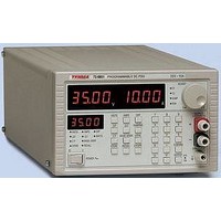
POWER SUPPLY, BENCH, 35V
Manufacturer
TENMA
Datasheet
1.72-6851.pdf
(33 pages)
Specifications of 72-6851
Power Supply Output Type
Variable
No. Of Outputs
1
Output Voltage
35V
Output Current
10A
Load Regulation
0.01%
Length
350.52mm
Width
210.82mm
Height
132.08mm
Output Type
Variable
Calibrated
No
Rohs Compliant
NA
Lead Free Status / RoHS Status
na


Tenma 72-6851 & 72-6853 Instruction manual
Current Meter Damping
Output On/Off
Store Settings
Recall Settings
Thermal Trip
Connection to the Load
Output Terminals
Sense Terminals
The output current meter damping is toggled on and off by pressing the DAMPING key. When
damping is on the DAMP LED will also be on.
The output is alternately turned on and off by pressing the OUTPUT key. The status is shown by
the ON LED next to the key.
The instrument contains 25 stores each capable of holding the entire set-up. The stored data is
non-volatile and is retained while power is off.
To save the instrument set-up to a store press the STORE key. The status display will show the
number of the last store which was accessed. This store may be used or a new store number
may be entered from the numeric key pad. When the required value is displayed press the
CONFIRM key to store the data in that store. Pressing the ESCAPE key will exit without making
any changes.
The instrument contains 25 stores each capable of holding the entire set-up. The stored data is
non-volatile and is retained while power is off.
To recall the instrument set up from a store press the RECALL key. The status display will show
the number of the last store which was accessed. This store may be used or a new store number
may be entered from the numeric key pad. When the required value is displayed press the
CONFIRM key to recall the data from that store. Pressing the ESCAPE key will exit without
making any changes.
If the instrument overheads a thermal trip will occur and the main displays will show the triP
message. The output will then be shut down, i.e. the output will be switched off. This condition will
persist until the instrument cools to below the trip temperature value, when the output will be
usable again.
Connection to the front panel output terminals can be made with 4mm plugs, spade terminals or
wire ends. To minimise voltage drop, the connecting leads to the load should be of an adequate
wire gauge and be kept short. Load wires should also be twisted together to reduce inductance.
The output is fully floating and either terminal can be connected to ground or raised by up to
300V peak above true ground; however, such voltages are hazardous and great care should be
taken.
The current limit can be set to limit the continuous output current to levels down to 10mA.
However, in common with all precision bench power supplies, a capacitor is connected across the
output to maintain stability and good transient response. This capacitor charges to the output
voltage, and short circuiting of the output will produce a short current pulse as the capacitor
discharges which is independent of the current limit setting.
To overcome errors introduced by connecting lead resistance at higher currents (10mΩ of lead
resistance will drop 0.2V at 20 Amps) the remote sending facility should be used. Remove the
two shorting links made between the rear output and sense terminals and connect the sense
terminals directly to the load; the power connections may be made from either the front or rear
terminals. To ensure good coupling between the output and sense, the sense wires should be
twisted with their corresponding output leads before the output leads are twisted together.
The voltage drop in each output lead must not exceed 1V.
www.tenma.com
9
Related parts for 72-6851
Image
Part Number
Description
Manufacturer
Datasheet
Request
R

Part Number:
Description:
TENMA DESOLDERING STATION, ADJUSTABLE TEMPERATURE: 410-900 DEG F, HEATER: 24 V AT 48 W, WEIGHT: 4.5 LBS, POWER: 110/120 VAC, INCLUDES: IRON HOLDER, GUN TYPE HANDLE, DIMENSIONS: (W X H X D) 8 1/4 X 6 X 6
Manufacturer:
TENMA


Part Number:
Description:
POWER SUPPLY, BENCH, 30V
Manufacturer:
TENMA
Datasheet:
Part Number:
Description:
POWER SUPPLY, BENCH, 30V
Manufacturer:
TENMA
Datasheet:
Part Number:
Description:
POWER SUPPLY, BENCH, 60V
Manufacturer:
TENMA
Datasheet:
Part Number:
Description:
POWER SUPPLY, BENCH, 18V
Manufacturer:
TENMA
Datasheet:

Part Number:
Description:
POWER SUPPLY, BENCH, 30V
Manufacturer:
TENMA
Datasheet:

Part Number:
Description:
POWER SUPPLY, BENCH, 30V/5V
Manufacturer:
TENMA
Datasheet:

Part Number:
Description:
POWER SUPPLY, BENCH, 30V/5V/12V
Manufacturer:
TENMA
Datasheet:

Part Number:
Description:
POWER SUPPLY, BENCH, 30V
Manufacturer:
TENMA
Datasheet:


Part Number:
Description:
Ribbon Cable Assembly, Header To Header, 1 Foot
Manufacturer:
Grayhill Inc
Part Number:
Description:
RS-232 To RS-422/485 Converter With 5V Operation
Manufacturer:
Grayhill Inc
Datasheet: