UEP-3.3/4500-D12-C Murata Power Solutions Inc, UEP-3.3/4500-D12-C Datasheet - Page 5
UEP-3.3/4500-D12-C
Manufacturer Part Number
UEP-3.3/4500-D12-C
Description
DC/DC TH 4.5A 12-3.3V UEP
Manufacturer
Murata Power Solutions Inc
Series
UEPr
Specifications of UEP-3.3/4500-D12-C
Product
Isolated
Output Power
15 W
Input Voltage Range
10 V to 18 V
Number Of Outputs
1
Output Voltage (channel 1)
3.3 V
Output Current (channel 1)
4.5 A
Isolation Voltage
1.5 KV
No. Of Outputs
1
Input Voltage
10V To 18V
Power Rating
14.85W
Output Voltage
3.3V
Output Current
4.5A
Approval Bodies
EN / UL
Supply Voltage
12V
Dc / Dc Converter Case Style
Through Hole
Rohs Compliant
Yes
Lead Free Status / Rohs Status
Lead free / RoHS Compliant


Input Overvoltage/Undervoltage Shutdown and Start-Up Threshold
Under normal start-up conditions, devices will not begin to regulate until the
ramping-up input voltage exceeds the Start-Up Threshold Voltage (35V for
"D48" models). Once operating, devices will not turn off until the input voltage
drops below the Undervoltage Shutdown limit (34V for "D48" models). Subse-
quent re-start will not occur until the input is brought back up to the Start-Up
Threshold. This built in hysteresis prevents any unstable on/off situations from
occurring at a single input voltage.
Input voltages exceeding the input overvoltage shutdown specification listed in
the Performance/Functional Specifications will cause the device to shutdown. A
built-in hysteresis of 0.6 to 1.6 Volts for all models will not allow the converter
to restart until the input voltage is sufficiently reduced.
The two 6 Amp models do not feature overvoltage shutdown and withstand
surges to 100V without shutting down. For custom overvoltage protection,
contact DATEL.
Input Reverse-Polarity Protection
If the input-voltage polarity is accidentally reversed, an internal diode will
become forward biased and likely draw excessive current from the power
source. If the source is not current limited (<10A) nor the circuit appropriately
fused, it could cause permanent damage to the converter.
On/Off Control
The input-side, remote On/Off Control function (pin 3) can be ordered to oper-
ate with either polarity (negative polarity available for 12 and 15 Volt models
only). Positive-polarity devices (standard, no part-number suffix) are enabled
when pin 3 is left open or is pulled high (+13V to V
–Input, pin 2, (see Figure 2). Positive-polarity devices are disabled when pin 3
is pulled low (0-0.8V with respect to –Input). Negative-polarity devices are off
when pin 3 is open or pulled high (+2.4V to +10V), and on when pin 3 is pulled
low (0-0.5V). See Figure 3.
Figure 2. Driving the Positive Polarity On/Off Control Pin
www.murata-ps.com
IN
applied with respect to
Dynamic control of the remote on/off function is best accomplished with a
mechanical relay or an open-collector/open-drain drive circuit (optically iso-
lated if appropriate). The drive circuit should be able to sink appropriate current
(see Performance Specs) when activated and withstand appropriate voltage
when deactivated.
Applying an external voltage to pin 3 when no input power is applied to the
converter can cause permanent damage to the converter.
Start-Up Time
The V
crosses the turn-on threshold point, and the fully loaded output voltage enters
and remains within its specified accuracy band. Actual measured times will
vary with input source impedance, external input/output capacitance, and load.
The UEP Series implements a soft start circuit that limits the duty cycle of the
PWM controller at power up, thereby limiting the Input Inrush current.
The On/Off Control to V
input voltage applied but is turned off via the On/Off Control pin. The specifica-
tion defines the interval between the time at which the converter is turned on
and the fully loaded output voltage enters and remains within its specified
accuracy band. Similar to the V
start-up time is also governed by the internal soft start circuitry and external
load capacitance.
Current Limiting
When output increases to 120% to 190% of the rated output current, the DC/DC
converter will go into a current limiting mode. In this condition the output
voltage will decrease proportionately with increases in output current, thereby
maintaining a somewhat constant power dissipation. This is commonly
referred to as power limiting. Current limit inception is defined as the point
where the full-power output voltage falls below the specified tolerance. See
Performance/Functional Specifications. If the load current being drawn from
the converter is significant enough, the unit will go into a short circuit condi-
tion. See “Short Circuit Condition.”
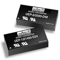
Ultra-High Density, 2" x 1", 1.2-6 Amp,15-30 Watt DC/DC’s
IN
to V
OUT
Single Output UEP Models
Figure 3. Driving the Negative Polarity On/Off Control Pin
start-up time is the interval of time where the input voltage
Technical enquiries email: sales@murata-ps.com, tel:
OUT
start-up time assumes the converter has its nominal
IN
to V
OUT
start-up, the On/Off Control to V
MDC_UEP Models.B02 Page 5 of 11
+1 508 339 3000
OUT
Related parts for UEP-3.3/4500-D12-C
Image
Part Number
Description
Manufacturer
Datasheet
Request
R

Part Number:
Description:
DC/DC Converters & Regulators 15W 24Vto3.3V 4500mA
Manufacturer:
Murata Power Solutions Inc
Datasheet:
Part Number:
Description:
DC/DC Converters & Regulators 15W 24Vto3.3V 4500mA
Manufacturer:
Murata Power Solutions Inc
Datasheet:
Part Number:
Description:
DC/DC TH 4.5A 48-3.3V UEP
Manufacturer:
Murata Power Solutions Inc
Datasheet:
Part Number:
Description:
DC/DC TH 6A 48-3.3V UEP
Manufacturer:
Murata Power Solutions Inc
Datasheet:
Part Number:
Description:
DC/DC TH 4.5A 12-3.3V UEP
Manufacturer:
Murata Power Solutions Inc
Datasheet:

Part Number:
Description:
POWER OVER ETHERNET MODULE
Manufacturer:
Murata Power Solutions Inc
Datasheet:

Part Number:
Description:
POWER OVER ETHERNET MODULE
Manufacturer:
Murata Power Solutions Inc
Datasheet:

Part Number:
Description:
POWER OVER ETHERNET MODULE
Manufacturer:
Murata Power Solutions Inc
Datasheet:

Part Number:
Description:
POWER OVER ETHERNET MODULE
Manufacturer:
Murata Power Solutions Inc
Datasheet:

Part Number:
Description:
Power Inductors 2.2mH1.4A
Manufacturer:
Murata Power Solutions Inc
Datasheet:

Part Number:
Description:
Transformers 5Vin 5Vout 200mA 4000Vdc 1:1.33 turn
Manufacturer:
Murata Power Solutions Inc
Datasheet:

Part Number:
Description:
POWER SUPPLY
Manufacturer:
Murata Power Solutions Inc
Datasheet:

Part Number:
Description:
DPM LED MINI 2VDC 3.5DIG LP RED
Manufacturer:
Murata Power Solutions Inc
Datasheet:

Part Number:
Description:
CONV DC/DC 1W 5VIN 5VOUT SIP SGL
Manufacturer:
Murata Power Solutions Inc
Datasheet:

Part Number:
Description:
CONV DC/DC 1W 5VIN 3.3V SIP SGL
Manufacturer:
Murata Power Solutions Inc
Datasheet: