SNAP-AIV-8 OPTO 22, SNAP-AIV-8 Datasheet - Page 3
SNAP-AIV-8
Manufacturer Part Number
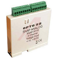
SNAP-AIV-8
Description
SNAP 8-Ch -10VDC To +10VDC Analog Input Module
Manufacturer
OPTO 22
Type
Inputr
Datasheet
1.SNAP-AIMA.pdf
(42 pages)
Specifications of SNAP-AIV-8
Brand/series
SNAP Series
Input Type
Analog
Input, Range
–10 to +10/–5 to +5 Volts
Isolation Voltage
1500 V
Mounting Type
DIN Rail
Number Of Channels
8
Primary Type
Control
Resolution
0.4 mV at 10 V/ 0.2 mV at 5.5 V
Voltage, Supply
5 VDC
Voltage Rating
5VDC
Current Rating
170mA
Length
90mm
External Width
82.55mm
External Depth
18.796mm
Accessory Type
Analog Voltage Input Module


Installation
Note module and processor compatibility in the following
table:
All modules can be used with SNAP PAC rac ks and can be
placed in any position on the rack. Two- and four-channel
modules (except the SNAP-AIRTD-10) can also be used with
legacy SNAP M-series and B-series mounting racks. (For more
information on using legacy hardware, see form #1688, the
SNAP PAC System Migration Technical Note.)
Modules snap securely into place in the row of connectors on
the mounting rack. Each module connector has a number.
Analog input modules and other types of SNAP I/O modules
are mounted on the module connectors starting at module
position zero.
Modules require a special tool (provided) for removal.
32-channel inputs
8-channel inputs
SNAP-AIRTD-10
4-channel inputs
2-channel inputs
(except SNAP-
AIRTD-10)
SNAP Analog Input Modules
© 2011 Opto 22. All rights reserved. Dimensions and specifications are subject to change. Brand or product names used herein are trademarks or registered trademarks of their respective companies or organizations.
Modules
SALES 800-321-6786 • 951-695-3000 • FAX 951-695-3095 • sales@opto22.com • SUPPORT 800-835-6786 • 951-695-3080 • FAX 951-695-3017 • support@opto22.com
SNAP PAC R-series controllers and
SNAP PAC brains, including Wired+Wire-
less models
SNAP PAC R-series controllers and
SNAP PAC brains, including Wired+Wire-
less models
Also the following legacy brains:
SNAP Ethernet, SNAP Simple, SNAP
Ultimate; SNAP-DNP-ASDS; SNAP OEM
SNAP PAC R-series controllers and
SNAP PAC brains, including Wired+Wire-
less models
Also the following legacy brains:
SNAP Ethernet, SNAP Simple, SNAP
Ultimate; SNAP-DNP-ASDS; SNAP OEM;
serial SNAP brains (B3000, Modbus, Pro-
fibus); B3000-HA; B6
Compatible I/O Processors
The following diagram shows part of a SNAP PAC mounting
rack.
1.
2.
3.
4.
5.
For faster, easier field wiring installation and maintenance,
use SNAP TEX cables and breakout boards. See Opto 22 form
#1756, the SNAP TEX Cables & Breakout Boards Data Sheet, for
compatibility and specifications.
Place the rack so that the module connector numbers
are right-side up, with zero on the left, as shown in the
diagram above. (If your rack has screw connectors, the
screw connectors will be at the bottom.)
Position the module over the module connector,
aligning the small slot at the base of the module with
the retention bar on the rack. When positioning modules
next to each other, be sure to align the male and female
module keys at the tops of the modules before snapping
a module into position.
With the module correctly aligned, push on the module
to snap it into place.
(Optional) Use standard 4-40 x 1/4 truss-head Phillips
hold-down screws to secure both sides of each module.
CAUTION: Do not over-tighten screws.
Follow the wiring diagrams beginning on
attach modules to the devices they monitor. Most
modules accept up to 14 AWG wire; the SNAP-AITM-8
accepts a maximum of two solid 18 AWG wires.
Opto 22 • 43044 Business Park Drive • Temecula, CA 92590-3614 • www.opto22.com
Processor
connector
Module
position zero
Module connectors
page 4
Retention bar
to
PAGE
3
Related parts for SNAP-AIV-8
Image
Part Number
Description
Manufacturer
Datasheet
Request
R

Part Number:
Description:
POWER SUPPLY, SWITCH MODE, 24V
Manufacturer:
OPTO 22
Datasheet:
Part Number:
Description:
Ethernet, I/O Brain, Rack Mount, 5.0 VDC 0.1 VDC @ 1.0 A; RS-232
Manufacturer:
OPTO 22
Datasheet:

Part Number:
Description:
Programmable Controller
Manufacturer:
OPTO 22
Datasheet:

Part Number:
Description:
Controllers
Manufacturer:
OPTO 22
Datasheet:

Part Number:
Description:
Brains; SNAP; 32-Channel; Digital Board; Pamux Protocol
Manufacturer:
OPTO 22
Datasheet:
Part Number:
Description:
Programmable Logic Controller
Manufacturer:
OPTO 22
Datasheet:

Part Number:
Description:
Power Monitoring Module
Manufacturer:
OPTO 22
Datasheet:

Part Number:
Description:
I/O Module
Manufacturer:
OPTO 22
Datasheet:

Part Number:
Description:
G4 DIGITAL I/O MODULE
Manufacturer:
OPTO 22
Datasheet:

Part Number:
Description:
Programmable Controller
Manufacturer:
OPTO 22
Datasheet:

Part Number:
Description:
Solid State Relays, Accessories
Manufacturer:
OPTO 22
Datasheet:
