Tel +1 (717) 767-6511
Fax +1 (717) 764-0839
www.redlion.net
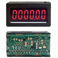
MODEL MDMU - MINIATURE DISPLAY MODULE COUNTER/TIMER
DESCRIPTION
circuit board mounted package. It is designed to operate from a 5 VDC power
supply. It has a 6 digit LCD, with 0.35" high digits, and 3 selectable decimal
points. In the timer modes, a flashing annunciator is supplied to indicate that the
signal input of the MDMU is active. The displays are available in positive image
reflective (black digits, reflective background) or negative image transmissive
(illuminated digits, dark background) with red or yellow/green backlighting.
available for determining the basic operation. In most applications, the MS and
DP inputs are hard wired to select the appropriate function (counter or timer)
and counter decimal point position.
appropriate levels (Hardware selection). Decimal points may also be set using
the DP Inputs (Hardware selection).
the appropriate levels (Hardware selection). The timing range increments
available are 1 msec, 10 msec, 100 msec, 1 sec, 0.1 min, 1 min, 0.01 hr, 0.1 hr,
and 1 hr. The TIMER ACTIVE annunciator will flash at a 1 Hz rate when the
input to the timer is activated.
DIMENSIONS
In inches (mm)
PRINTED CIRCUIT BOARD MOUNT UNIT
The MDMU is a complete 6 digit Counter/Timer in a small panel or printed
The MDMU has four Mode Select and two Decimal Point Select inputs
The COUNTER mode is selected by setting the Mode select inputs to the
The TIMER mode and range is selected by setting the Mode Select inputs to
NOTE: BACKLIGHT MODELS: 0.50" (12.7)
PANEL MOUNT UNIT
REFLECTIVE MODELS: 0.31" (8.0)
NOTE: BACKLIGHT MODELS: 0.56" (14.2)
REFLECTIVE MODELS: 0.37" (9.4)
1.81 (46.0)
1.65 (41.9)
Note: Recommended minimum clearance behind the panel for mounting clip installation is 2.25" (57.2)W x 1.5" (38.1)H
(22.9)
0.90
(26.9)
1.06
0.06
(1.5)
NOTE
SEE
NOTE
SEE
0.14 (3.56) MIN.
0.2 (5.08) MAX.
1
SPECIFICATIONS
1. DISPLAY: 6 Digit LCD, 0.35" (8.89 mm) high characters, available in
2. POWER REQUIREMENTS:
3. DECIMAL POINTS:
0.19 (4.8)
handling to the same degree required by standard CMOS integrated
circuits. Units should be stored in the conductive package used to ship the
device. Containers should be opened and units handled only on a
conductive table top by personnel wearing wrist-strap grounding equipment.
These devices have the same protection circuits as standard CMOS devices
to prevent damage to inputs due to nominal over-voltage.
0.14 (3.56) MIN.
0.2 (5.08) MAX.
positive image reflective (black digits, reflective background) or negative
image transmissive (illuminated digits, dark background) with red or yellow/
green backlighting.
Reflective Versions: 5.0 VDC ±10% 100 μA max.
Backlight Versions: 5.0 VDC ±10% 25 mA max.
Timer: Determined by the timing mode selected.
Counter: 3 programmable positions.
WITH YELLOW/GREEN OR RED BACKLIGHTING
LCD, POSITIVE REFLECTIVE OR NEGATIVE TRANSMISSIVE
COUNTER & TIMER ALL IN A SINGLE UNIT
COUNT POSITIVE OR NEGATIVE EDGE
9 RANGES IN TIMER MODE
SELECTABLE DECIMAL POINTS
5 VDC POWERED
PANEL MOUNT OR PC BOARD MOUNT
This device contains CMOS circuitry which requires special anti-static
(23.6
0.93
+.03
-.02
+.8
-.5
RECOMMENDED PCB LAYOUT
)
Ø 0.042 (1.07)
PANEL CUT-OUT
0.12 (3.1)
0.10 (2.5)
UNIT OUTLINE
R 0.06 MAX., 4PL.
(1.5)
THRU, 15 PL.
1.68
(42.7
CAUTION
+.03
-.02
+.8
-.5
)
Bulletin No. MDMU-F
Drawing No. LP0391
Released 12/09